Lithographic apparatus and method to determine beam characteristics

a technology of lithographic apparatus and beam characteristics, applied in the direction of radiation measurement, printing, instruments, etc., can solve the problems of limited options in the lithographic system, different imaging quality of horizontal and vertical structures on the substrate, and no quick or automated procedure in order

Active Publication Date: 2005-03-22
ASML NETHERLANDS BV
View PDF5 Cites 4 Cited by
  • Summary
  • Abstract
  • Description
  • Claims
  • Application Information

AI Technical Summary

Problems solved by technology

Until now, only limited options are available in a lithographic system to determine such beam quality characteristics and to control such characteristics.
Specifically, when a radiation beam lacks a proper dimensioning and homogeneity, the ellipticity, for example, of the projection beam can be affected, causing a different imaging quality of horizontal and vertical structures on a substrate.
Although considered relevant for achieving optimal illumination conditions, no quick or a...

Method used


Image

  • Lithographic apparatus and method to determine beam characteristics
  • Lithographic apparatus and method to determine beam characteristics
  • Lithographic apparatus and method to determine beam characteristics

Examples


Embodiment Construction

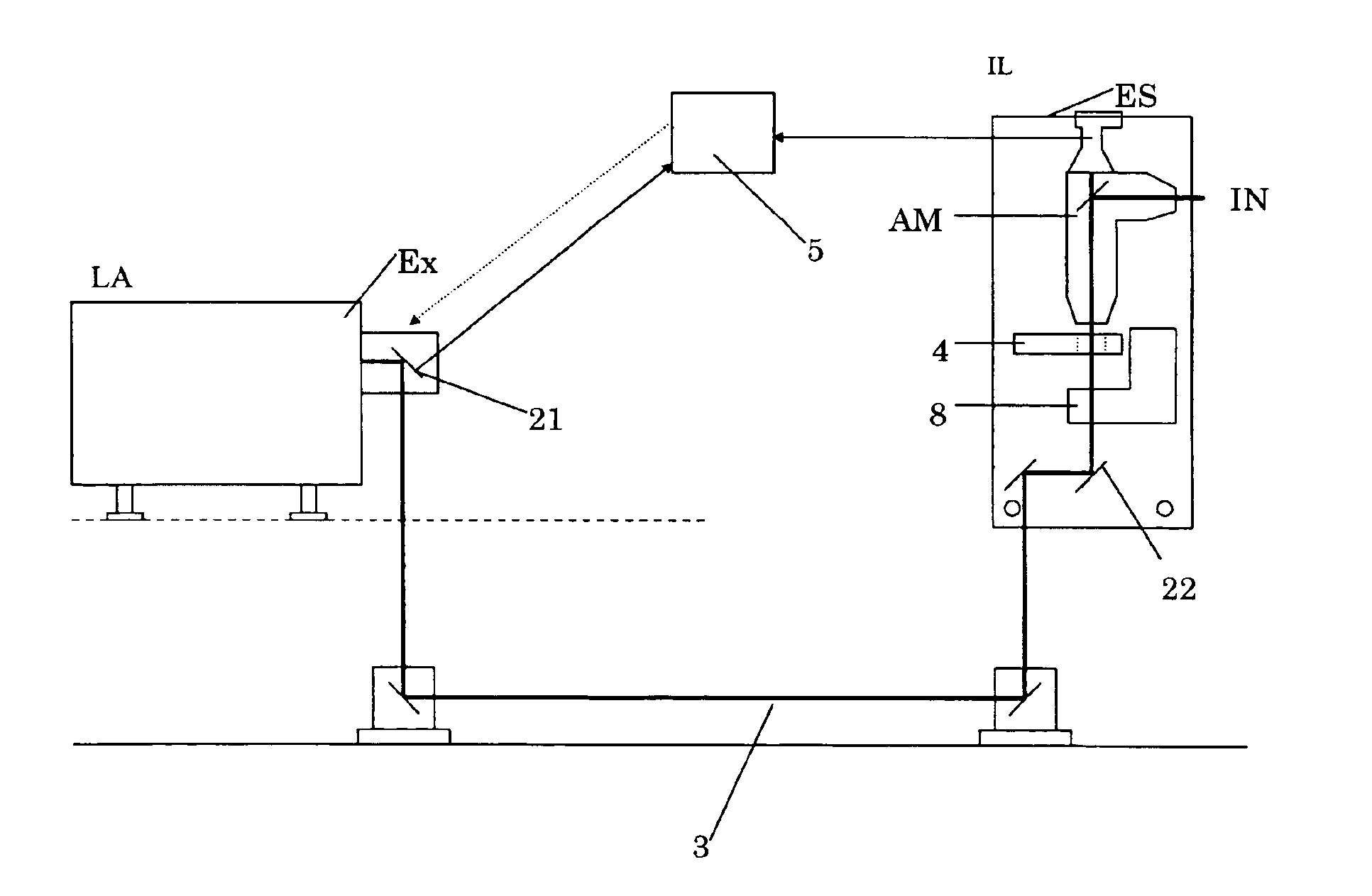
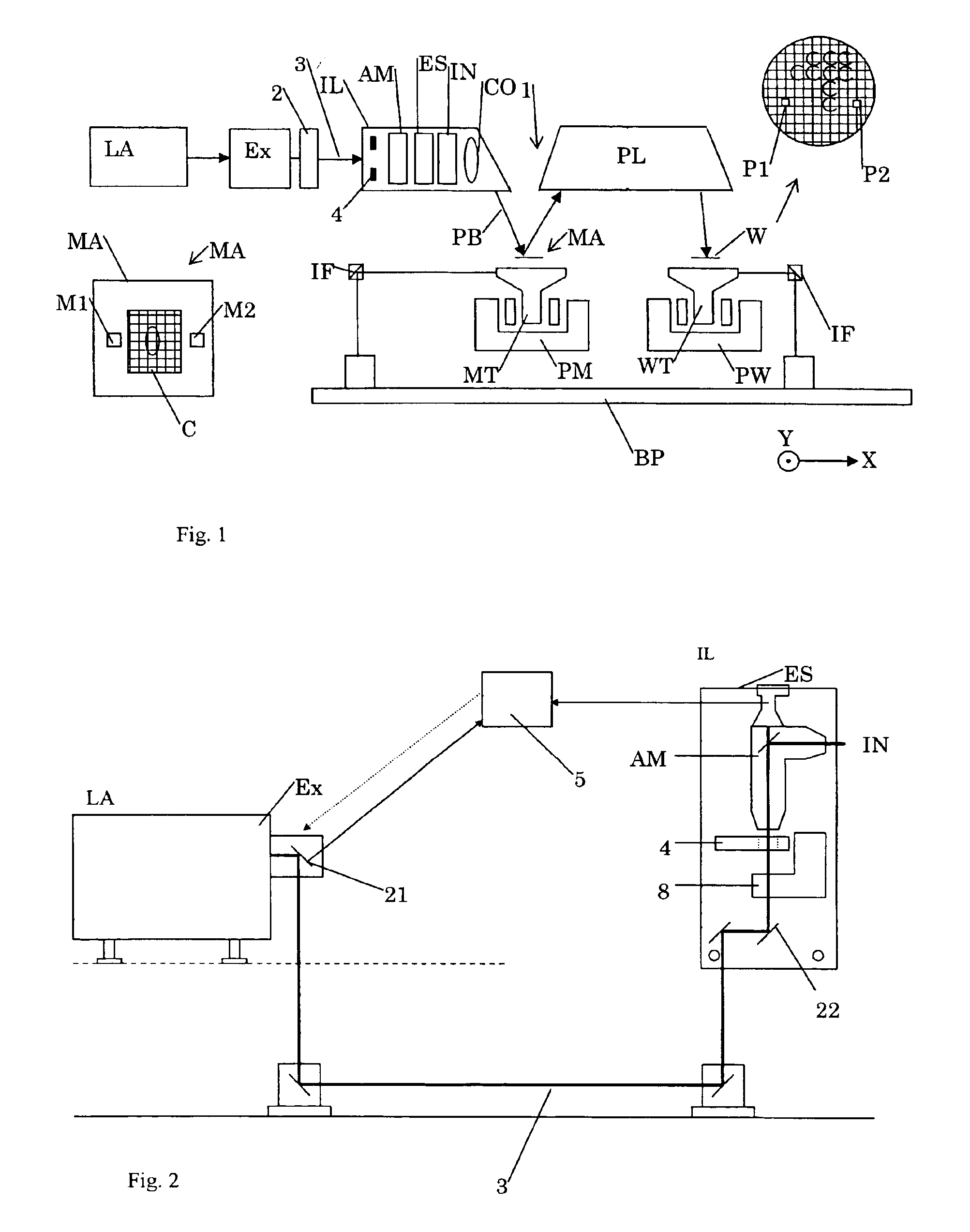
FIG. 1 schematically depicts a lithographic apparatus 1 according to a particular embodiment of the invention. The apparatus comprises:a radiation system LA, Ex, 2, IL, for supplying a projection beam PB of radiation (e.g. radiation in the deep ultraviolet region);a first object table (mask table) MT provided with a mask holder for holding a mask MA (e.g. a reticle), and connected to first positioning means PM for accurately positioning the mask with respect to item PL;a second object table (substrate table) WT provided with a substrate holder for holding a substrate W (e.g. a silicon wafer), and connected to second positioning means PW for accurately positioning the substrate with respect to item PL; anda projection system (“lens”) PL for imaging an irradiated portion of the mask MA onto a target portion C (e.g. comprising one or more dies) of the substrate W.

As here depicted, the apparatus is of a reflective type (e.g., has a reflective mask). However, in general, it may also be o...


PUM


Abstract

A lithographic apparatus is provided that has an aperture, a detector configured to detect an intensity of a radiation beam directed through the aperture and a processor configured to vary the intensity of the radiation beam through the aperture by a relative movement of the radiation beam and the aperture and to calculate a beam size of the radiation beam from the detected intensity and relative movement. Alternatively or in addition, a lithographic apparatus may include a focusing element configured to focus a part of a radiation beam in a focus plane, an aperture arranged in the focus plane of the focusing element, a detector configured to detect an intensity of the part of the radiation beam through the aperture, and a processor configured to vary the intensity of the radiation beam through the aperture by a change in a pointing direction of the radiation beam and to calculate a beam divergence of the radiation beam from the detected intensity and pointing direction. The apparatus offers a means to determine beam quality characteristics such as beam size and/or beam divergence.

Description

This application claims priority from European patent application EP 02079722.1 filed Nov. 13, 2002, herein incorporated in its entirety by reference.FIELDThe present invention relates to apparatus and methods to determine beam characteristics.BACKGROUNDThe term “patterning device” as here employed should be broadly interpreted as referring to means that can be used to endow an incoming radiation beam with a patterned cross-section, corresponding to a pattern that is to be created in a target portion of the substrate; the term “light valve” can also be used in this context. Generally, the said pattern will correspond to a particular functional layer in a device being created in the target portion, such as an integrated circuit or other device (see below). Examples of such a patterning device include:A mask. The concept of a mask is well known in lithography, and it includes mask types such as binary, alternating phase-shift, and attenuated phase-shift, as well as various hybrid mask...

Claims


Application Information

Patent Timeline
IPC IPC(8): G03F7/20G01B15/00G01T1/29G01B11/10G21K5/00G21K5/02G21K5/04H01L21/027
CPCG03F7/70141G03F7/70133G03F7/20
Inventor TEEUWEN, LEONARDUS JOHANNES HENDRIKUS GERARDUS WILHELMUS
Owner ASML NETHERLANDS BV
Why Eureka
Try Eureka