Compact optical fingerprint capturing and recognition system

a fingerprint recognition and optical technology, applied in the field of fingerprint recognition systems, can solve the problems of weak reflected light beam at such contact points, generating greater uncertainty in determining the optical path in the system, and the above system suffers from some severe disadvantages, so as to achieve relatively compact, small circuitry, and convenient operation.

Inactive Publication Date: 2005-03-22
SECUGEN CORP
View PDF460 Cites 104 Cited by
  • Summary
  • Abstract
  • Description
  • Claims
  • Application Information

AI Technical Summary

Benefits of technology

Each of the above two described embodiments of a fingerprint imaging apparatus having a biometric circuit are advantageously relatively simple,

Problems solved by technology

Consequently, the reflected light beam at such contact points are weaker.
However, the above system suffers from some severe disadvantages.
Light paths that are not parallel to the optical axis are not well defined and generate greater uncertainty in determining the optical paths in the system.
Second, such systems can suffer from significant image distortions.
The optical assembly 200 also suffers from some disadvantages of earlier optical structures.
First, there is the problem of image distortion because non-parallel light rays are transmitted from the object to the lens assembly 215.
Otherwise, if the lens is close enough to the optical prism such that a condition approximating total internal reflection is not met, then some of the light rays from the object will be lost and will not be captured by the s

Method used


Image

  • Compact optical fingerprint capturing and recognition system
  • Compact optical fingerprint capturing and recognition system
  • Compact optical fingerprint capturing and recognition system

Examples


Embodiment Construction

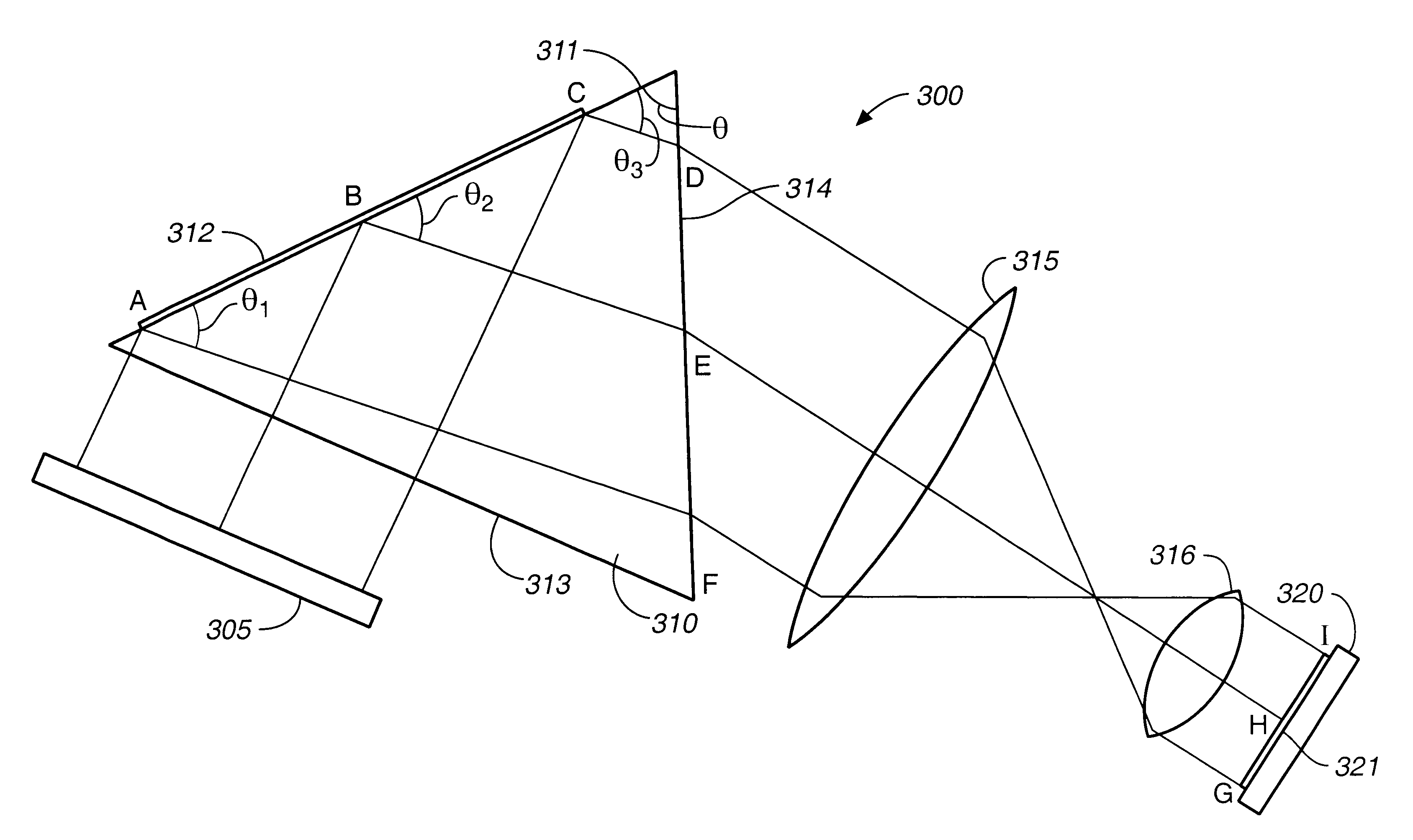
FIG. 4 is a schematic diagram of the optical structure of the optical fingerprint capturing and recognition system of the present embodiment of the invention. The optical structure 300 comprises an illuminating light source 305, an optical prism 310, an object lens assembly 315, an eyepiece lens assembly 316, and an image sensor 320.

Illuminating light source 305 is a plane light source, such as an LED array. As incident surface 313 of optical prism 310 is translucent, it uniformly disperses the incoming light received from illuminating light source 305 such that optical prism 310 receives light of uniform intensity from incident surface 313. The incident surface 313 may be made translucent by sand papering or other means known to those skilled in the art. In one alternative embodiment, a translucent layer may be placed between the illuminating light source 305 and the optical prism 310. In yet another embodiment, illuminating light source 305 may be a uniform light source.

Optical pr...


PUM


Abstract

An apparatus and method for acquiring an image of a patterned object such as a fingerprint including a light refracting device, a focusing lens, a light source, and a biometric circuit for detecting the presence of a patterned object such as a fingerprint at the light refracting device. Incident light from the light source is projected through a light receiving surface of the light refracting device and is directly reflected off an imaging surface. The resulting image is projected through the focusing lens. The focusing lens has a diameter which is larger than the projection of the patterned object through the light refracting device.

Description

BACKGROUND OF THE INVENTION1. Field of the InventionThe present invention generally relates to fingerprint capturing and recognition systems. More specifically, the present invention relates to compact optical fingerprint capturing and recognition systems.2. Description of the Related ArtFIG. 1 shows a schematic diagram of an earlier optical fingerprint capturing and recognition system. In FIG. 1, an optical recognition system 100 includes an illuminating light source 105, an optical prism 110, a lens assembly 115, an image sensor 120, and a storage and processing unit 125. The illuminating light source 105, which may, for example, be a light emitting diode (LED), generates a light ray that is transmitted to the optical prism 110. The optical prism 110 has an apex angle θ that is approximately 45 degrees. In an optical fingerprint capturing and recognition system, the apex angle is defined as the angle opposite to the incident surface of the optical prism, i.e., the surface of the p...

Claims


Application Information

Patent Timeline
IPC IPC(8): G06K9/00G06K5/00
CPCG06K9/00046G06V40/1324
Inventor TENG, HARRY H.JO, SUNG-CHAN
Owner SECUGEN CORP
Why Eureka
Try Eureka