Optical fiber communication system using optical phase conjugation as well as apparatus applicable to the system and method of producing the same

a technology of optical phase conjugation and applied in the field of optical fiber communication system, can solve the problems of expensive and complicated regenerative repeater, limited transmission capacity of optical fiber, and inability to achieve the effect of reducing noise and compensating effectively

Inactive Publication Date: 2005-03-22
FUJITSU LTD
View PDF21 Cites 14 Cited by
  • Summary
  • Abstract
  • Description
  • Claims
  • Application Information

AI Technical Summary

Benefits of technology

By such parameter setting, the chromatic dispersion and the nonlinearity are compensated for effectively. Further, since the waveform distortion exhibits a minimum value at the system midpoint using the two phase conjugators, the phase conjugators need not be disposed intermediately of the transmission line. According to the present invention, not only the optical Kerr effect but also other nonlinearities such as a Raman effect are compensated for.
Preferably, a plurality of optical amplifiers are provided on the optical path including the first, second and thir

Problems solved by technology

However, the transmission capacity by an optical fiber is actually limited by system designing.
The most significant limitation arises from waveform distortion by chromatic dispersion which occurs in an optical fiber.
This method, however, has a problem in that a regenerative repeater which is expensive and complicated is required and an electronic circuit of the regenerative repeater limits the bit rate of a main signal.
How

Method used


Image

  • Optical fiber communication system using optical phase conjugation as well as apparatus applicable to the system and method of producing the same
  • Optical fiber communication system using optical phase conjugation as well as apparatus applicable to the system and method of producing the same
  • Optical fiber communication system using optical phase conjugation as well as apparatus applicable to the system and method of producing the same

Examples


first embodiment

Referring to FIG. 7, there is shown the present invention. For the first optical fiber 4, two such DD-DCFs 24 as were used in the demonstration test are adopted. An optical amplifier 26 is provided on the input side of each of the DD-DCFs 24 so that the power of a signal beam to be supplied to each DD-DCF 24 may have a predetermined level. The first portion 81 of the second optical fiber 8 is formed from a plurality of optical fibers 28 connected in cascade connection. Between each adjacent ones of the optical fibers 28, an optical amplifier 30 is provided in order to keep the optical power in the first portion 81 substantially constant. The second portion 82 of the second optical fiber 8 is formed from a plurality of optical fibers 32. Between each adjacent ones of the optical fibers 32, an optical amplifier 34 is provided in order to keep the optical power in the second portion 82 substantially constant.

Particularly in the present embodiment, at the system midpoint 16, an optical ...

second embodiment

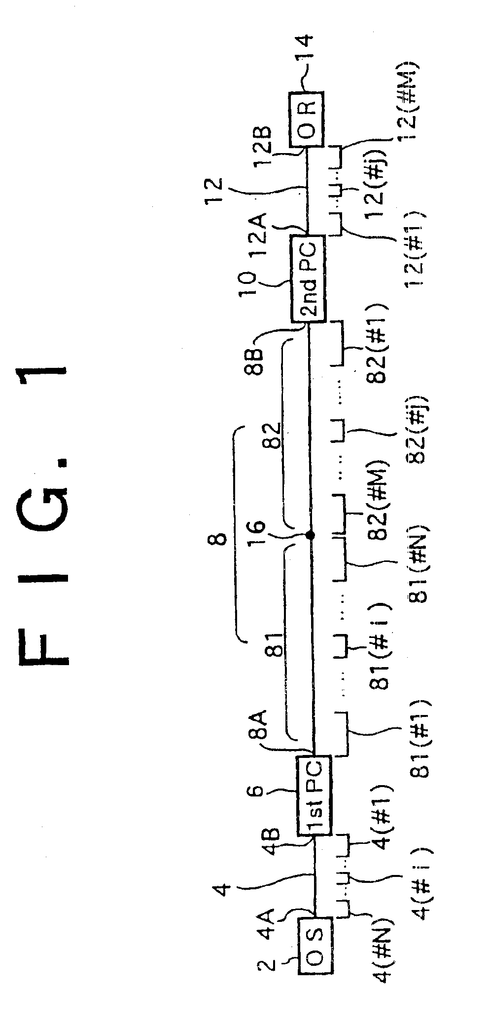
Referring to FIG. 10, there is shown an optical communication system showing the present invention. The present embodiment is characterized, in contrast with the basic construction of FIG. 1, in that a branching unit 58 is provided at the system midpoint 16 of the second optical fiber 8.

A signal beam outputted from the optical transmitter 2 is supplied to the first phase conjugator 6 by the first optical fiber 4. The first phase conjugator 6 converts the received signal beam into and outputs a phase conjugate beam. The phase conjugate beam outputted from the first phase conjugator 6 is supplied to the branching unit 58 by the first portion 81 of the second optical fiber B. The branching unit 58 branches the received phase conjugate beam into first and second branch beams. The first and second branch beams are supplied to phase conjugators 10-1 and 10-2 through second portions 82-1 and 82-2 of the second optical fiber 8, respectively. The phase conjugator 10-1 converts the received f...

third embodiment

Referring to FIG. 11, there is shown the present invention. Here, in order to expand and apply the basic construction of FIG. 1 to WDM (wavelength division multiplex), an optical multiplexer (MUX) 62 and an optical demultiplexer (DE-MUX) 64 are used.

Optical transmitters 2-1, . . . , n (n is an integer larger than 1) individually output signal beams having different wavelengths from each other. The signal beams are supplied to the optical multiplexer 62 through optical fibers 4-1, . . . , n individually corresponding to the first optical fiber 4 of FIG. 1. The optical multiplexer 62 wavelength division multiplexes the received signal beams and outputs a WDM signal beam. Then, the WDM signal beam is supplied to the first phase conjugator 6. Here, since the optical fibers 4-1, . . . , n for exclusive use are provided individually for the optical transmitters 2-1, . . . , n, setting of parameters according to the present invention is possible for each wavelength channel. In other words,...


PUM


Abstract

An optical fiber communication system according to the present invention has, for example, first and second phase conjugators. The first phase conjugator converts a signal beam from a first optical fiber into a first phase conjugate beam. The first phase conjugate beam is supplied to the second phase conjugator by a second optical fiber. The second phase conjugator converts the first phase conjugate beam into a second phase conjugate beam. The second phase conjugate beam is transmitted by a third optical fiber. The second optical fiber is composed of a first portion located between the first phase conjugator and a system midpoint and a second portion located between the system midpoint and the second phase conjugator. The total dispersion of the first optical fiber substantially coincides with the total dispersion of the first portion, and the total dispersion of the second portion substantially coincides with the total dispersion of the third optical fiber. By the construction, waveform distortion by chromatic dispersion or nonlinearity is compensated for.

Description

TECHNICAL FIELDThis invention relates to an optical fiber communication system using optical phase conjugation as well as an apparatus applicable to the system and a method of producing the same.BACKGROUND ARTAs a result of development of a silica optical fiber of low loss, many optical fiber communication systems wherein an optical fiber is used for a transmission line have been put into practical use. An optical fiber itself has a very broad band. However, the transmission capacity by an optical fiber is actually limited by system designing. The most significant limitation arises from waveform distortion by chromatic dispersion which occurs in an optical fiber. Further, while an optical fiber attenuates an optical signal, for example, at the rate of approximately 0.2 dB / km, the loss by such attenuation has been compensated for by adoption of optical amplifiers including an erbium-doped fiber amplifier (EDFA).Chromatic dispersion often simply called dispersion is a phenomenon where...

Claims


Application Information

Patent Timeline
IPC IPC(8): H04B10/18G02F1/35H04B10/2507H04B10/2519H04B10/2525H04B10/2531H04B10/2537H04B10/255H04B10/2557H04B10/275H04B10/278H04B10/291H04B10/524H04B10/54H04B10/588H04J14/02
CPCH04B10/2531H04B10/2563H04B10/2543
Inventor WATANABE, SHIGEKI
Owner FUJITSU LTD
Why Eureka
Try Eureka