
File system including non-volatile semiconductor memory device having a plurality of banks

a non-volatile semiconductor and memory device technology, applied in the field of file systems, can solve the problems of lowering operation speed, requiring large amount of time, and certain limits for erasures, and achieve the effect of high speed

Inactive Publication Date: 2005-03-22
RENESAS ELECTRONICS CORP
View PDF7 Cites 40 Cited by
  • Summary
  • Abstract
  • Description
  • Claims
  • Application Information

AI Technical Summary

Benefits of technology

An object of the present invention is to provide a file system including a non-volatile semiconductor memory device, which can be executed at high speed.
Another object of the present invention is to provide a file system including a non-volatile semiconductor memory device, which has a long operation life.
A further object of the present invention is to provide a file system including a non-volatile semiconductor memory device, which can back up data even if unexpected power shut-off occur.
A yet further object of the present invention is to provide a file system including a non-volatile semiconductor memory device, which has a long operation life by averaging the number of erasures for each bank in the non-volatile semiconductor memory device.
A still further object of the present invention is to provide a file system including a non-volatile semiconductor memory device, which has a long operation life by making the number of bank erasures as small as possible in the non-volatile semiconductor memory device.

Problems solved by technology

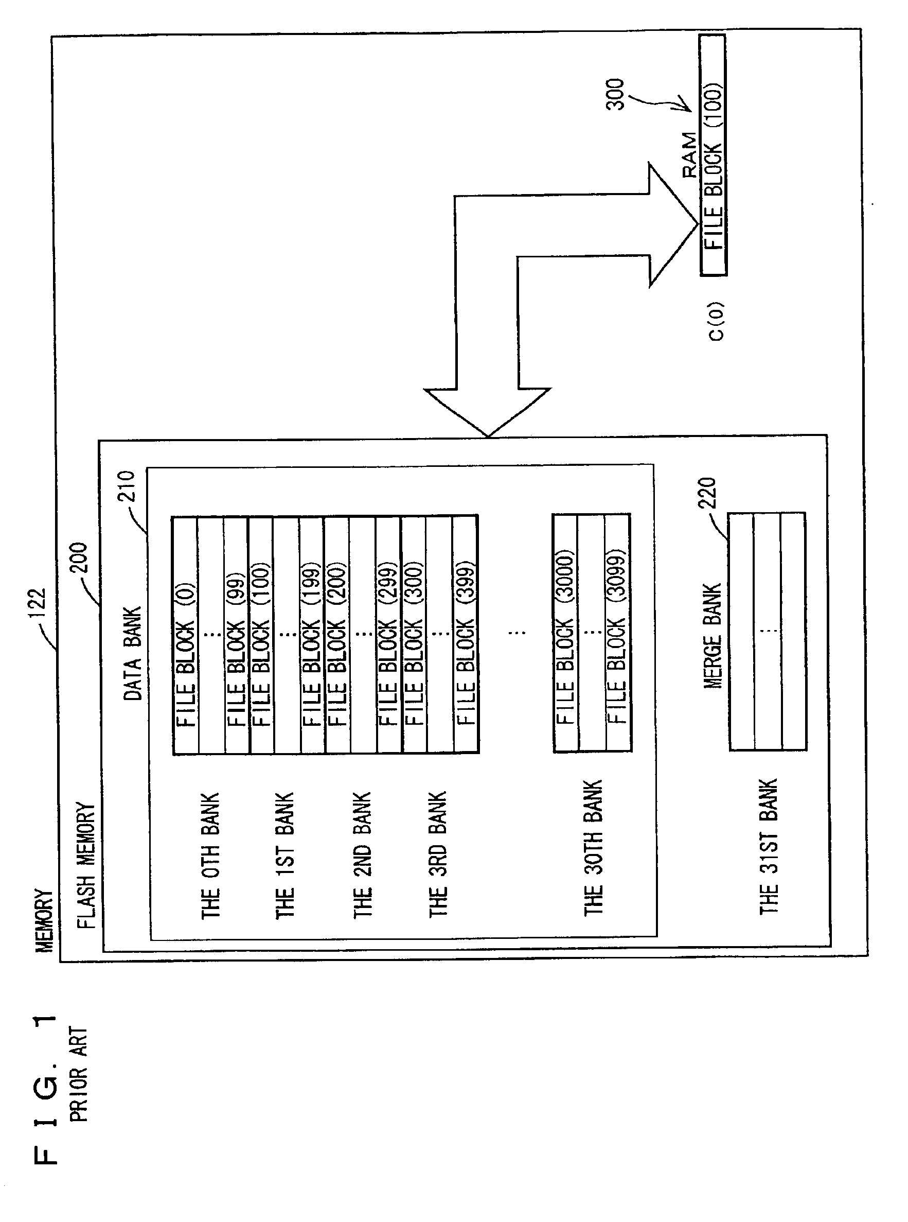
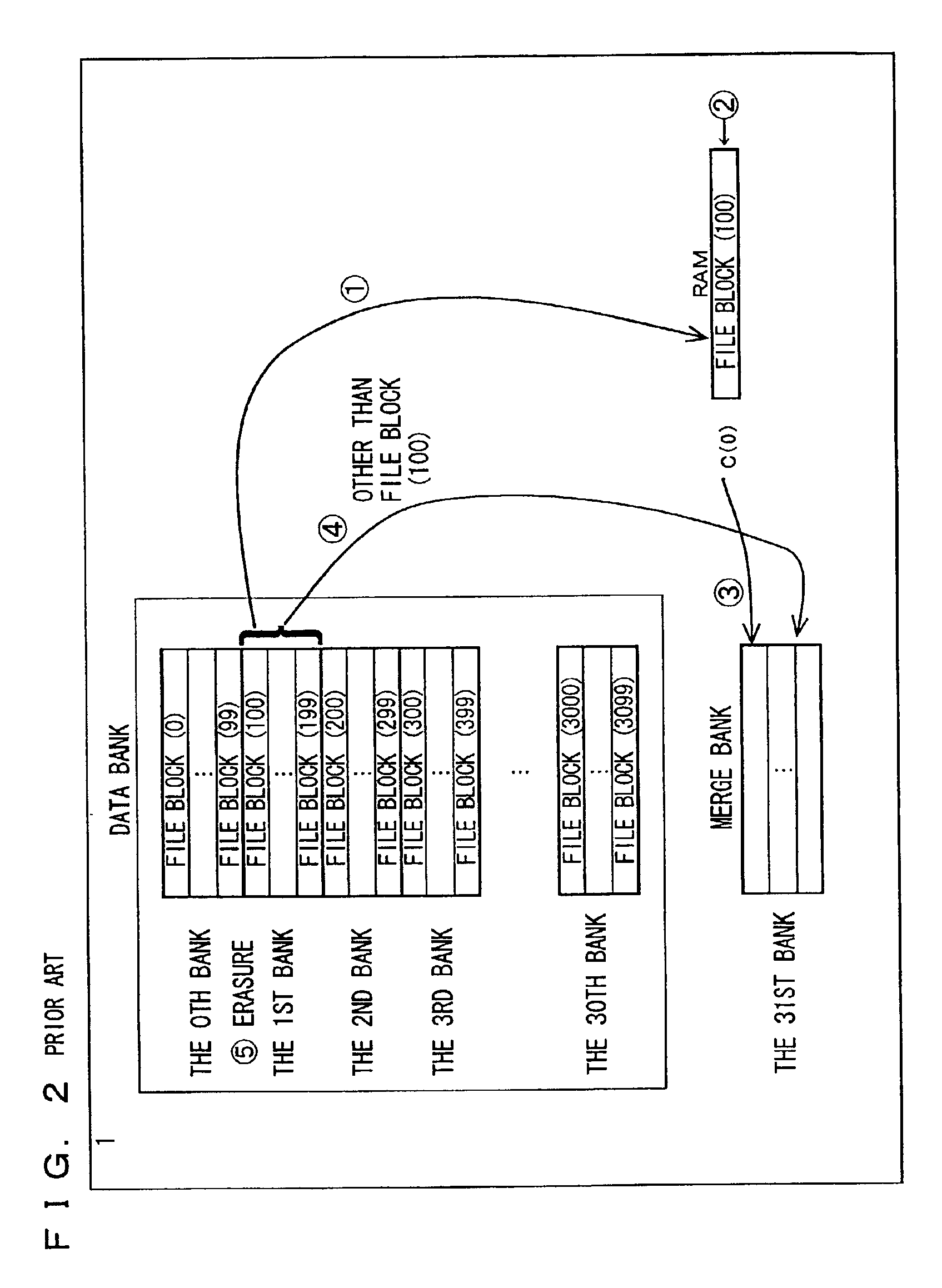
This raises a problem as described below when a file system is constructed on the flash memory.
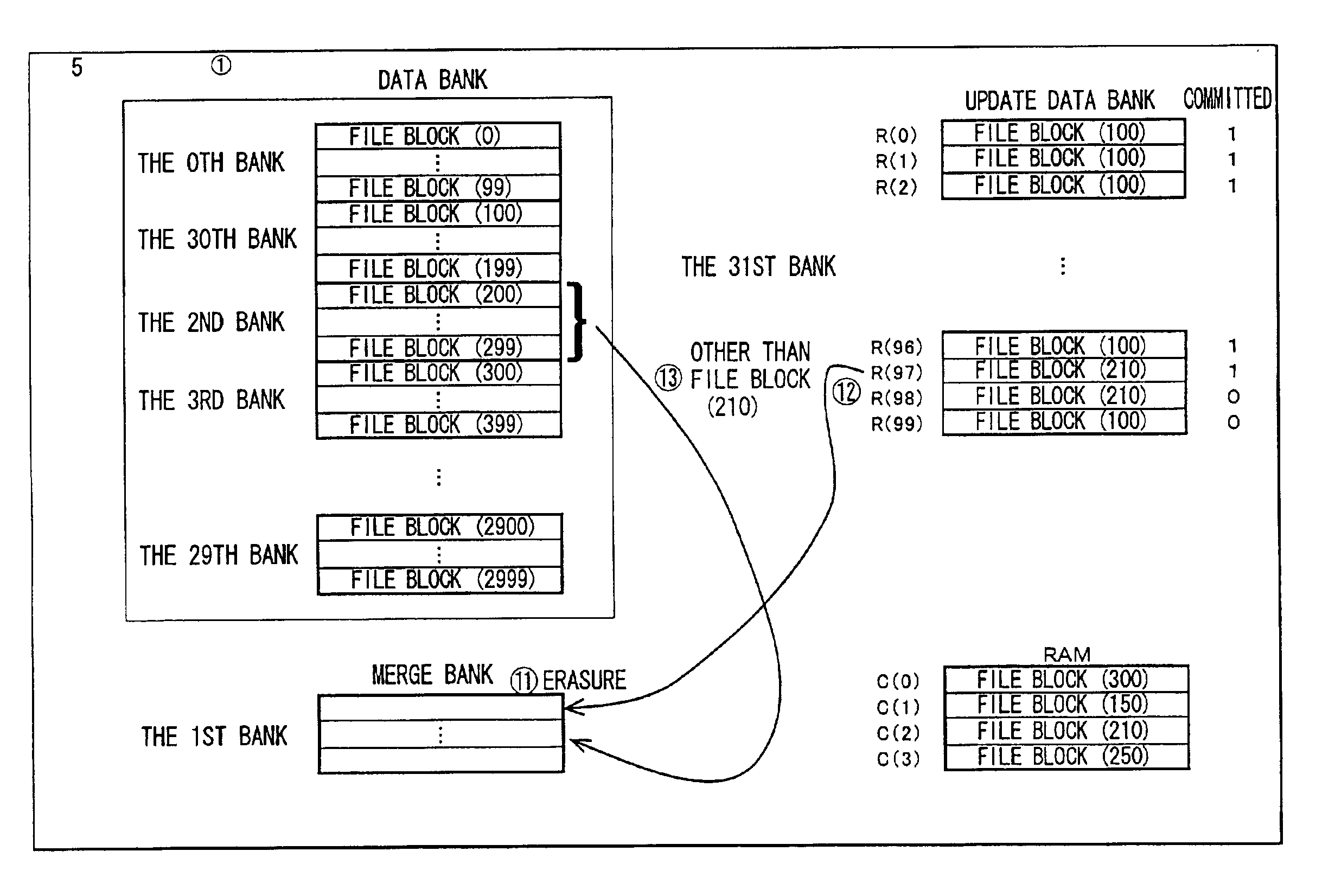
Thus, in order to update five file blocks, banks must be erased five times. As described earlier, a large amount of time is required for such erasure by the bank, and there is a certain limit for the number of erasures.
However, in the conventional file system, bank erasure frequently occurs, lowering operation speed and shortening lifetime of the flash memory.
Moreover, in the conventional file system, if the power is shut off or reset with unexpected timing, the entire file system may be destroyed and hence become unworkable without reformat.
If this happens, the stored data will be lost.

Method used


Image

  • File system including non-volatile semiconductor memory device having a plurality of banks
  • File system including non-volatile semiconductor memory device having a plurality of banks
  • File system including non-volatile semiconductor memory device having a plurality of banks

Examples


first embodiment

A file system according to the present embodiment involves file control of a non-volatile ROM (a flash memory) that is erasable bank by bank. The file system is used for, in particular, equipment in which a flash memory is mounted for the purpose of rewriting data more than once, e.g., portable equipment such as a mobile phone, a PDA and a digital still camera.

FIG. 7 shows the configuration of a portable equipment 1020 in the form of a block diagram. As shown in FIG. 7, portable equipment 1020 includes a CPU (Central Processing Unit) 1200, a memory 1220, an entry key 1100, and a liquid crystal monitor 1040 that are interconnected via a bus. A program for controlling the file system according to the present embodiment is pre-stored in a non-volatile memory portion (a flash memory) of memory 1220. The hardware itself in the portable equipment shown in FIG. 7 is a typical one. Thus, the essential part of the present invention is the file system implemented by a program stored in a stor...

second embodiment

The file system according to the present embodiment executes a writing process different from that in the first embodiment described above. The other parts of the hardware configuration and the flow charts except for the process steps described below are similar to those in the first embodiment described above. Therefore, detailed description thereof will not be repeated here.

Referring to FIGS. 26A and 26B, the control structure of the writing process executed in the file system according to the present embodiment is described. It is noted that the process steps in FIGS. 26A and 26B that are the same as the ones in FIGS. 12A and 12B are denoted by the same step numbers. The processes thereof are also the same. Therefore, detailed description thereof will not be repeated here.

At S2000, after initializing variable I, CPU 1200 resets a cache full flag. At S2002, if there is no free space in cache area 3100 of RAM 3000, CPU 1200 sets the cache full flag. Thereafter, the copy_cache_to_ba...

third embodiment

The file system according to the present embodiment is implemented using an SRAM (Static Random Access Memory) having a backup power-supply for update data bank 2300 in the first embodiment. Referring to FIG. 31, the internal structure of the memory in the file system according to the present embodiment is descried. As shown in FIG. 31, the memory in the file system according to the present embodiment includes a flash memory 2101 constituted by data bank 2100 and merge bank 2200, and an SRAM2301 constituted by an update data bank. The configuration of the other parts and the flow charts except for the process steps described below are the same as those in the first embodiment described earlier. Therefore, detailed description thereof will not be repeated here.

As the file system according to the present embodiment is implemented using the SRAM as an update data bank, there is no limit for data writing to the update data bank, compared to the case where a flash memory is used for the ...


PUM


Abstract

A flash memory includes a data bank having a plurality of banks, a merge bank, and an update data bank. A file system using the flash memory includes a unit storing update data corresponding to a data rewrite command into the update data bank, a unit selecting the latest update data for each block from update data stored in the update data bank when the update data bank becomes full, and a processing unit processing the latest update data. The processing unit includes a unit storing latest update data into a merge bank, a unit selecting data associated with the latest update data from the data bank to store the selected data into the merge bank, and a unit setting the merge bank as a new data bank.

Description

BACKGROUND OF THE INVENTION1. Field of the InventionThe present invention relates to a file system of a computer system, and particularly to a file system using a non-volatile semiconductor memory device such as a flash memory or the like.2. Description of the Related ArtA flash memory is a type of an EEPROM (Electrically Erasable and Programmable ROM) which can be rewritten electrically, and has such characteristics that it is less expensive than a DRAM (Dynamic Random Access Memory), a backup power supply is unnecessary, the change of bits is irreversible, data is erased bank by bank, erasure of a bank requires time, and the number of bank erasures is limited.The flash memory having such characteristics is widely used as a data storage device in equipment such as a mobile phone, a PDA (Personal Digital Assistant), a digital still camera and the like. In such equipment, varieties of data to be stored have increased, leading to frequent operations such as saving, deleting and moving...

Claims


Application Information

Patent Timeline
Patent Type & Authority Patents(United States)
IPC IPC(8): G06F12/02G06F12/00G06F12/16
CPCG06F12/0246G06F12/0868G06F2212/1036G06F2212/222G06F2212/313G06F2212/7203G06F2212/7208G06F16/13
Inventor HAGIWARA, MASATOSAKAMOTO, MAMORU
Owner RENESAS ELECTRONICS CORP
Learn More