Orientation preserving angular swivel joint

a technology of angular swivel joints and orientation preservation, which is applied in the direction of gearing, mechanical control devices, instruments, etc., can solve the problems of enlarging the joint size, and the double angular swivel joint cannot be used as a snake robot joint, etc., and achieves a high mechanical advantage proportional to the radius of the robot. , compact, easy to control

Inactive Publication Date: 2005-03-29
CHOSET HOWIE +1
View PDF10 Cites 112 Cited by
  • Summary
  • Abstract
  • Description
  • Claims
  • Application Information

AI Technical Summary

Benefits of technology

It is another object of this invention to provide a joint, which is light, compact, strong and easily controllable. It is yet another object of this invention to provide a joint, which can be used in all kinds of mechanical robotic arms.
The joint in accordance with the present invention comprises two members and an angular bevel gear train that connects the two members of the joint. The gear train allows an actuator to be positioned along the axis of the joint while transferring forces to the periphery of the mechanism, thus creating a high mechanical advantage proportional to the radius of the robot. The gear train also minimizes the stresses and torques on the joint components. The joint is capable of producing high forces and resisting high loads, both being critical aspects of many snake robot applications. Preferably, the joint may produce a torque as high as about 5 Newton-Meters or higher with a safety factor of 2, and thus can preferably resist forces of the same order of magnitude. As the skilled person will appreciate, these values will depend on the particular application of

Problems solved by technology

Moreover, these joints present the disadvantage of being bulky since the top actuator is installed along axis 92a thus enlarging the joint size.
This means that relative rotation has occurs between the two members, and thus the double angular swivel joint cannot be used as a snake robot joint.
Such designs afford the robot limited capabilities and size.
However, this design has the disadvantage of being bulky and has the problem of twisting.
This design has irregularity in the universal joint and has a relatively small strength-to-size ratio.
Nonetheless, this joint is heavy and bulky.
Moreover, since the universal joint does not transfer rotational speed between the two members linearly, the joint is difficult to control and the bending speed is not constant.
Because the joint in mounted inside the robot, the size of the joint is limited and must be relatively small.
This small and hollow universal joi

Method used


Image

  • Orientation preserving angular swivel joint
  • Orientation preserving angular swivel joint
  • Orientation preserving angular swivel joint

Examples


Embodiment Construction

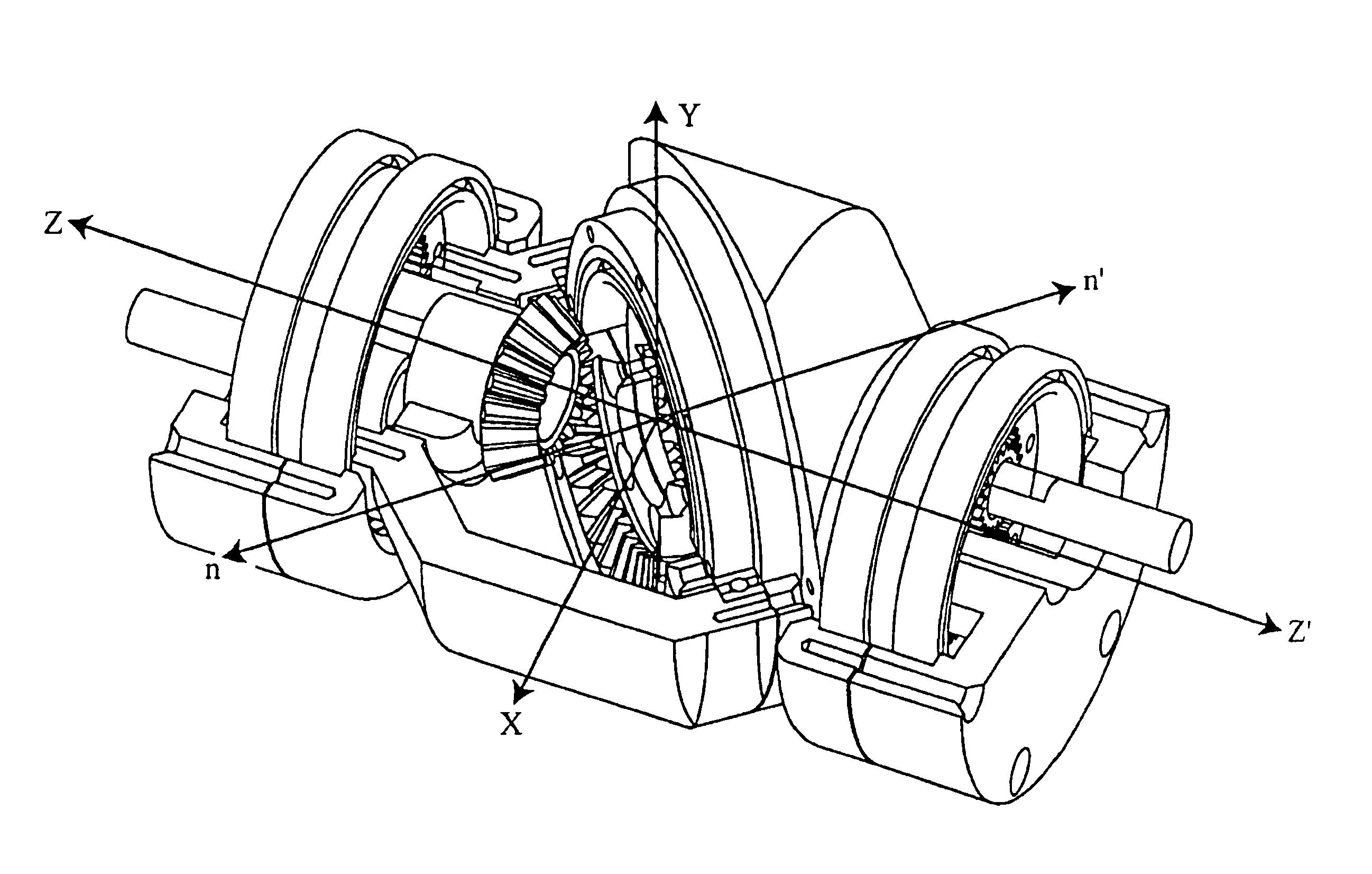
Turning to FIGS. 5a and 5b, the upper half subassembly 1 of the joint is shown. First bay 11 is coupled to obliquely cut upper cup 15 by first and second upper angular bearings 13. Bearings 13 allow upper cup 15 to rotate freely about axis OZ′ with respect to first bay 111 with minimal friction. Additionally, bearings 13 hold upper spur ear 10 into position as spur ear 10 is sandwiched between the two bearings 13, upper spur ear 10 being fixedly mounted on upper cup 15. Preferably, two bearings 13 are used to ensure free rotation of upper cup 15 about axis OZ′ with no or very minimal wobbling. Upper cup 15 and upper spur pinion gear 10 are preferably bolted together, preferably using a circular array of bolts. However, other ways known in the art of fixedly mounting, two elements may be used as well (e.g., welding). Thus, upper cup 15 and upper spur gear 10 may rotate as one rigid body. Bolting together the upper cup15 and upper spur gear 10 has the advantage that the two elements m...


PUM


Abstract

An orientation preserving angular swivel joint suitable for mechanical robotic arms and in particular snake robots, the joint comprising two members and an angular bevel gear train that connects the two members of the joint. The gear train allows an actuator to be positioned along the axis of the joint while transferring forces to the periphery of the mechanism, thus creating a high mechanical advantage proportional to the radius of the robot. The gear train is capable of transferring rotational motion between the two members with a constant ratio. Relative rotation between two bays of the joint does not take place, thereby preventing electrical wires running through the body of the snake from being twisted, and thus avoiding failure.

Description

BACKGROUNDA conventional revolute or a simple swivel joint is shown in FIG. 1. The conventional joint has one degree-of-freedom, since members 101 and 103 are only allowed to rotate about a single axis 102. An example of a simple swivel joint is the human elbow.FIG. 2 depicts a conventional double revolute robotic joint, which utilizes two actuators. The bottom actuator orients the bending plane 95 by rotating the whole assembly about axis 91a, and the top actuator bends the top member 92 within that plane by rotating member 92 about axis 92a. This joint has two independent degrees-of-freedom: orienting and bending. Since each degree-of-freedom is actuated by a different motor, the degrees-of-freedom are said to be decoupled. As it would be apparent to a person skilled in the art, the orientation of the top member 92 denoted by vector 94 changes as member 91 is rotated about axis 91a. The type of joint shown in FIG. 2 is not adequate for use in a snake robot because of the relative ...

Claims


Application Information

Patent Timeline
IPC IPC(8): B25J17/02B25J9/10
CPCB25J9/102B25J17/0275Y10T74/20305Y10T74/19688Y10T74/20329Y10T74/20317
Inventor CHOSET, HOWIESHAMMAS, ELIE
Owner CHOSET HOWIE
Why Eureka
Try Eureka