Method of and apparatus for tunable gas injection in a plasma processing system

Inactive Publication Date: 2005-03-29
TOKYO ELECTRON LTD
View PDF28 Cites 445 Cited by
  • Summary
  • Abstract
  • Description
  • Claims
  • Application Information

AI Technical Summary

Benefits of technology

[0023]The present invention is an apparatus and a method that enables the supersonic expansion of gases through arrays of specially designed “tunable” nozzles capable of adjusting the internal gas flow within the nozzle to adjust the nozzle gas exit pressure relative to the ambient chamber pressure. Part of the gas nozzle structure allows the position of the nozzle plug to be tran

Problems solved by technology

In particular, as critical dimensions continue to decrease and respective aspect ratios of various features, such as self align contacts, etc., continue to increase, the ability to transport etch reactants and/or deposition materials to (and remove etch products from) the bottom of high aspect ratio (HAR) vias and contacts becomes inherently more difficult.
This is primarily due to the lack of directionality of the neutral flow.
Due to the effusive nature of the gas introduction, two distinct features of the flow through these bores include very low “bulk” velocities in a particular direction (i.e., gas molecules do not move collectively in a preferred direction at high velocities) and an overall lack of directivity.
However, there are disadvantages to the first method.
For example, a separate injection plate must be machined for each distribution tested, and it cannot be adjusted without breaking the vacuum or low pressure environment.
However, the design can produce fairly complex and expensive plumbing arrangements for gas injection.
However, a shortcoming of this system is that the gas is not optimally directed at the wafer surface, so as to enhance the statistical probability of gas atoms or molecules appro

Method used


Image

  • Method of and apparatus for tunable gas injection in a plasma processing system
  • Method of and apparatus for tunable gas injection in a plasma processing system
  • Method of and apparatus for tunable gas injection in a plasma processing system

Examples


first through sixth embodiments

, respectively;

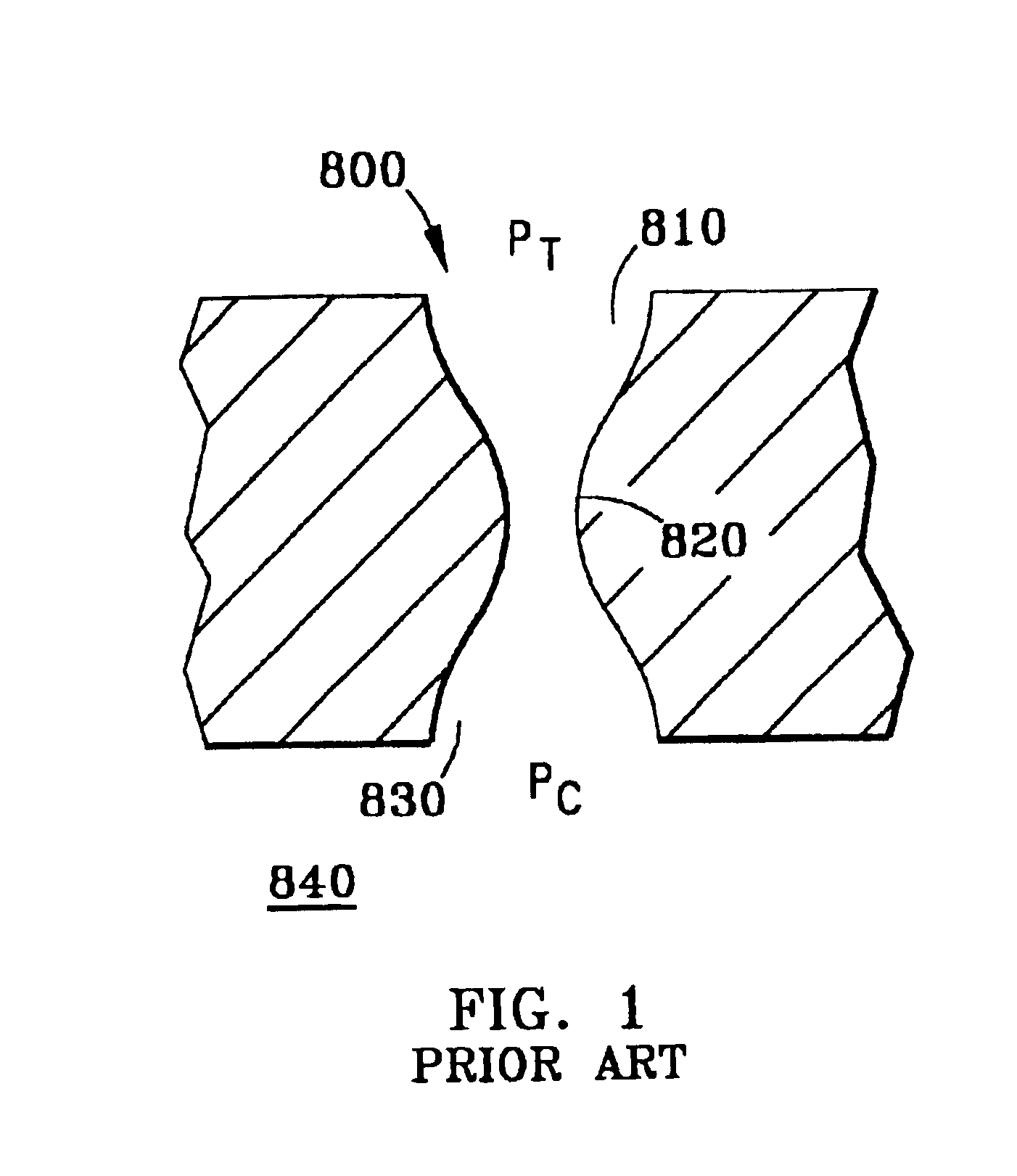
[0040]FIGS. 4A-4C are cross-sectional schematic diagrams of a section of a gas injection manifold operating in an under-expanded mode (FIG. 4A), a pressure-matched mode (FIG. 4B) and an over-expanded mode (FIG. 4C);

[0041]FIG. 5 is a plan view of a gas injection manifold having a radial arrangement of nozzle units;

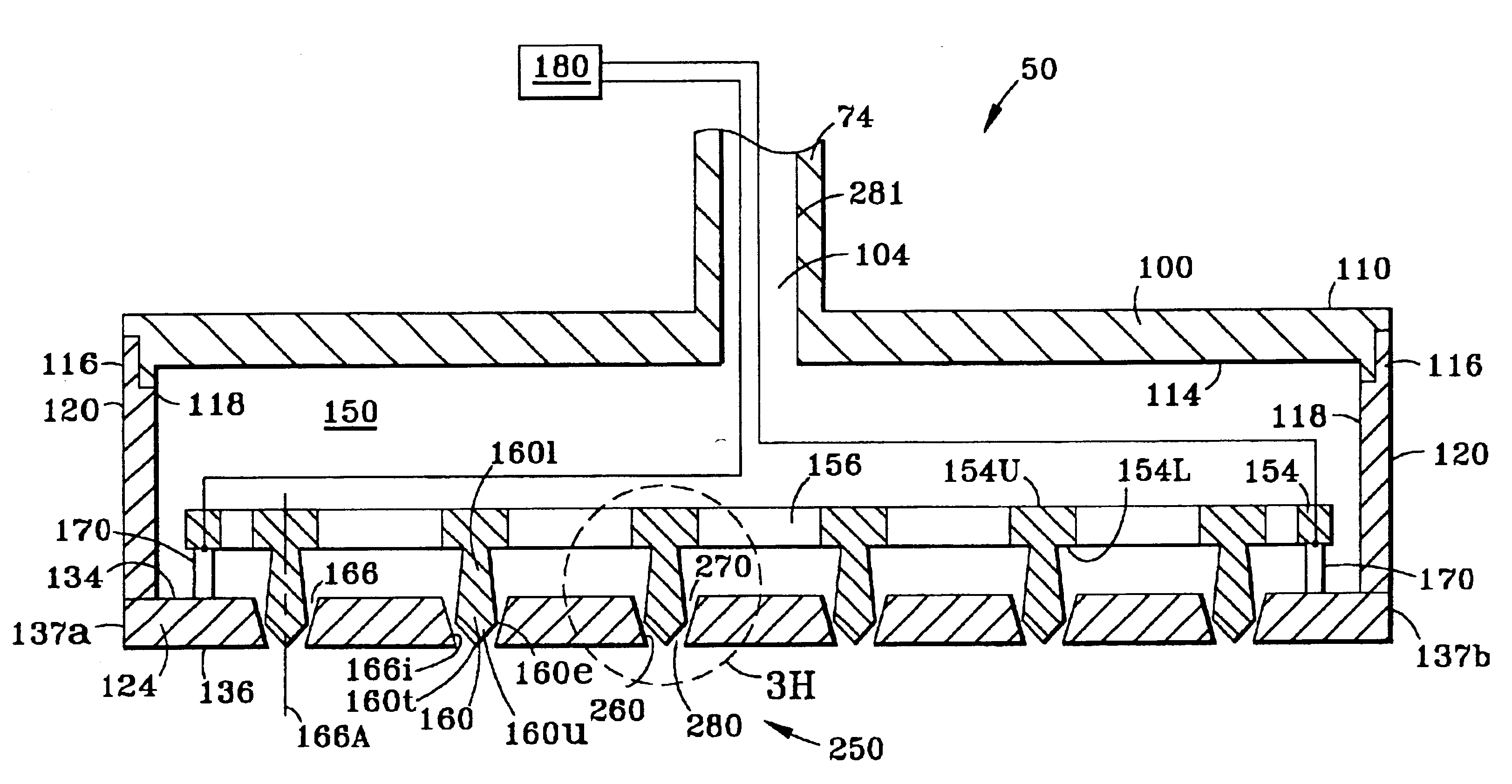
[0042]FIG. 6 is a cross-sectional schematic diagram of a gas injection manifold of the present invention, which includes a nozzle array plate having a nozzle array formed therein, wherein the nozzles in the nozzle array have a convergent-divergent double-conic cross-section;

[0043]FIG. 7 is a cross-sectional close-up schematic diagram of a nozzle of the gas injection manifold of FIG. 6;

[0044]FIG. 8 is a cross-sectional schematic diagram of a gas injection manifold according to the present invention similar to that of FIG. 6, but where the nozzles have a cylindrical upper section at the gas entrance end and a concave lower section at the gas exit end; and

[0045]...


PUM

PropertyMeasurementUnit
Dielectric polarization enthalpyaaaaaaaaaa
Pressureaaaaaaaaaa
Flow rateaaaaaaaaaa

Abstract

A method of and apparatus for providing tunable gas injection in a plasma processing system (10, 10′). The apparatus includes a gas injection manifold (50) having a pressurizable plenum (150) and an array of adjustable nozzle units (250), or an array of non-adjustable nozzles (502, 602), through which gas from the plenum can flow into the interior region (40) of a plasma reactor chamber (14) capable of containing a plasma (41). The adjustable nozzle units include a nozzle plug (160) arranged within a nozzle bore (166). A variety of different nozzle units are disclosed. The nozzle plugs are axially translatable to adjust the flow of gas therethrough. In one embodiment, the nozzle plugs are attached to a plug plate (154), which is displacable relative to an injection plate (124) via displacement actuators (170) connecting the two plates. The displacement actuators are controlled by a displacement actuator control unit (180), which is in electronic communication with a plasma processing system control unit (80). The gas flow into the chamber interior region is preferably controlled by monitoring the pressure in the plenum and in the chamber and adjusting the nozzle units accordingly. Where the nozzle units are not adjustable, a portion of the nozzles are sized to a first flow condition, and another portion of the nozzles are sized to a second flow condition.

Description

[0002]This is a continuation of International Application No. PCT / US01 / 09196 which was filed on Mar. 23, 2001, and also claims benefit of U.S. application Ser. No. 60 / 193,231, filed Mar. 30, 2000, the contents of both of which are incorporated herein in their entirety.FIELD OF THE INVENTION[0003]The present invention relates to plasma processing systems, and in particular, to methods of and apparatus for providing tunable gas injection in such systems.BACKGROUND OF THE INVENTION[0004]One of the key factors that affects the throughput of the fabrication of integrated circuits (IC) is the etch rate and / or deposition rate. In particular, as critical dimensions continue to decrease and respective aspect ratios of various features, such as self align contacts, etc., continue to increase, the ability to transport etch reactants and / or deposition materials to (and remove etch products from) the bottom of high aspect ratio (HAR) vias and contacts becomes inherently more difficult. This is p...

Claims


Application Information

Patent Timeline
IPC IPC(8): C30B25/14H01J37/32C23C16/44C23C16/455H01L21/205H01L21/3065
CPCC23C16/45565C23C16/45589H01J37/32449H01J37/3244C30B25/14
Inventor STRANG, ERIC J.
Owner TOKYO ELECTRON LTD
Why Eureka
Try Eureka