Exchange coupling film capable of improving playback characteristics

Inactive Publication Date: 2005-03-29
ALPS ALPINE CO LTD
View PDF6 Cites 20 Cited by
  • Summary
  • Abstract
  • Description
  • Claims
  • Application Information

AI Technical Summary

Benefits of technology

When the exchange coupling film is used for each magnetic detection element as described above, the wettability of the aforementioned seed layer surface can be improved remarkably compared to that heretofore attained and, therefore, both the unidirectional exchange bias magnetic field (Hex*) and the rate of resistance change (ΔR/R) in the fixed magnetic layer can be improved compared to those in the conventional case where the NiFeCr alloy or Cr, in which the compositional ratio of Cr has been 40 at % or less, have been used as the seed layer, and the smoothness of the surface of each layer formed on the seed layer can be improved.
By the improvement of the aforementioned smoothness, the ferromagnetic coup

Problems solved by technology

However, even when the seed layer is formed from the material containing

Method used


Image

  • Exchange coupling film capable of improving playback characteristics
  • Exchange coupling film capable of improving playback characteristics
  • Exchange coupling film capable of improving playback characteristics

Examples


first embodiment

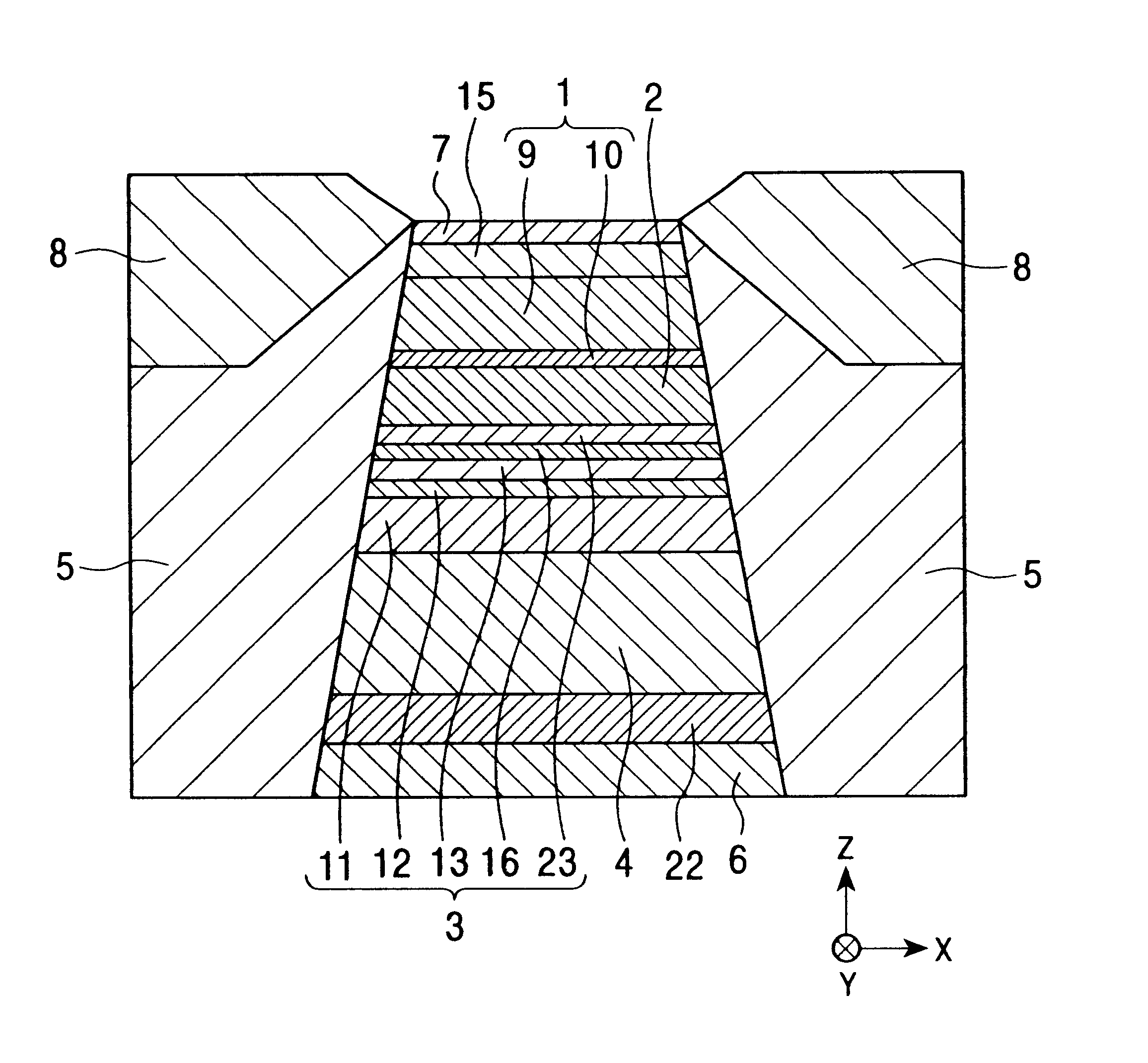
FIG. 1 is a sectional view of the whole structure of a magnetic detection element (single spin valve type magnetoresistance effect element) according to the present invention viewed from the surface facing a recording medium side. FIG. 1 is a cutaway view showing only the center portion of the element extending in the X direction.

This single spin valve type magnetoresistance effect element is placed on an end portion on the trailing side, etc., of a floating slider placed on the hard disk device so as to detect the recording magnetic field of the hard disk, etc. The movement direction of the magnetic recording medium, for example, hard disk, is the Z direction, and the direction of the leakage magnetic field from the magnetic recording medium is the Y direction.

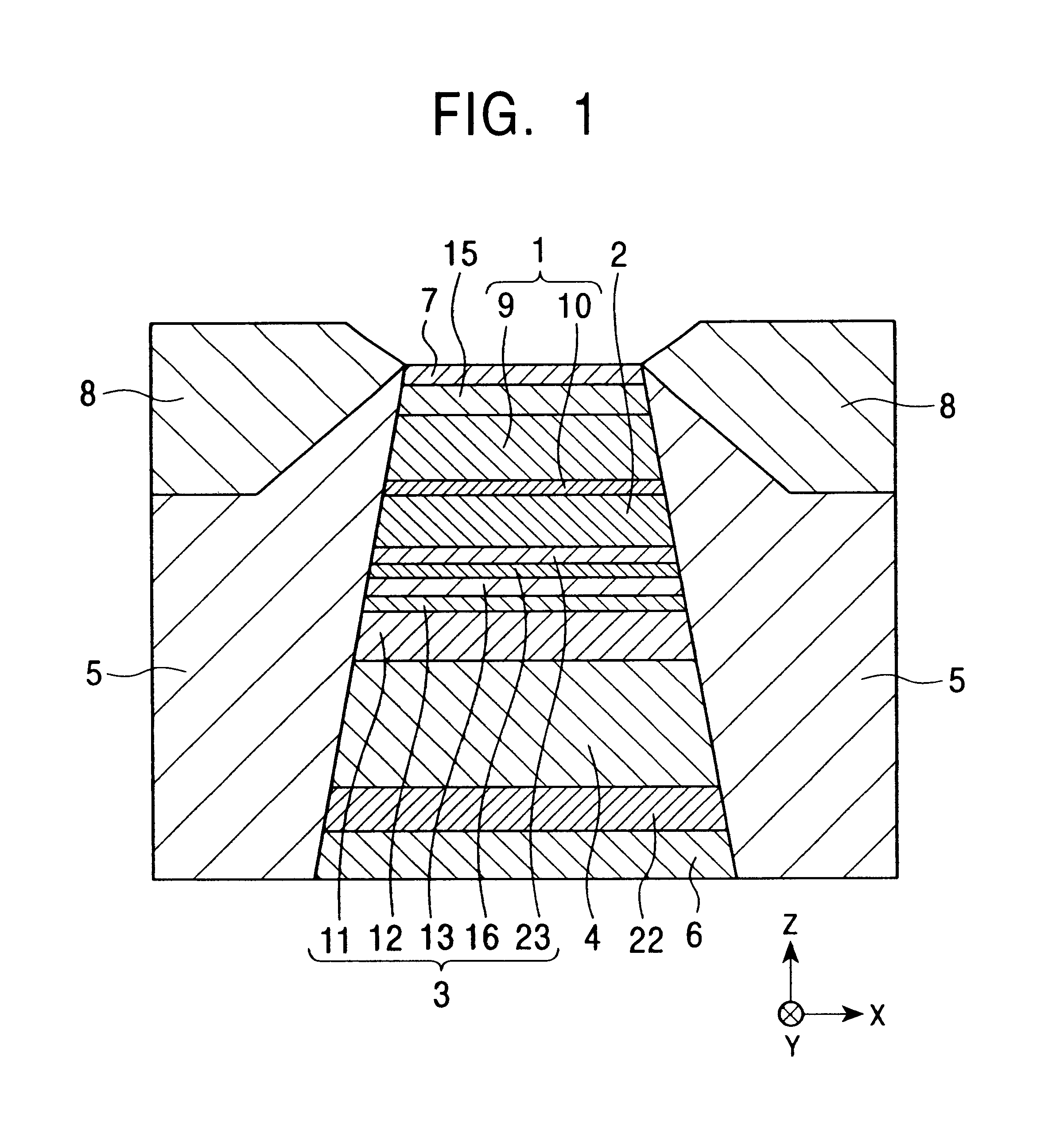
In FIG. 1, a substrate layer 6 formed from a non-magnetic material, for example, at least one element selected from the group consisting of Ta, Hf, Nb, Zr, Ti, Mo, and W, is formed at the bottom. On this substrate layer 6, a ...

examples

In the present invention, the crystal structure of the aforementioned seed layer, the unidirectional exchange bias magnetic field (Hex*), etc., are measured regarding Examples 1, 2, and 3 and Comparative example 1 using the seed layer formed from NiFeCr (the compositional ratio of Cr is 90 at %), Comparative examples 2 to 5 using the seed layer formed from Cr, Conventional examples 1 and 2 formed from NiFeCr (the compositional ratio of Cr is 40 at % or 23 at %), and Conventional example 3 in which no seed layer is formed.

The film configuration and film making condition of each Example, Comparative example, and Conventional example are shown in the following Table 1.

TABLE 1AverageUni-crystaldirectionalparticleexchangeRate ofFerro-diameterbiasresist-magneticin theSubstrateSeedmagneticancecouplingdirectionTEMlayer / layerfieldchangemagneticof filmphoto-FilmAnnealingseedcrystalHex*ΔR / Rfield Hinsurfacegraphconfigurationconditionlayerstructure(Oe) (A / m)(%)(Oe) (A / m)ÅExampleFIG. 6Si substrat...


PUM


Abstract

A seed layer is formed containing Cr and an element X (wherein the element X is Fe, Ni, etc.) on a substrate layer formed from Ta, etc. At this time, the compositional ratio of the aforementioned Cr is specified to be 80 at % or more, and the seed layer is formed to have a film thickness of 20 Å or more, but 130 Å or less. According to this, the wettability of the seed layer surface can be improved remarkably compared to that heretofore attained, the unidirectional exchange bias magnetic field and rate of resistance change in the fixed magnetic layer can be increased, and it becomes possible to make the smoothness of the surface of each layer on the aforementioned seed layer excellent.

Description

BACKGROUND OF THE INVENTION1. Field of the InventionThe present invention relates to an exchange coupling film which is composed of a seed layer, an antiferromagnetic layer, and a ferromagnetic layer in that order from the bottom, wherein the direction of magnetization of the aforementioned ferromagnetic layer is set in a specified direction due to an exchange coupling magnetic field generated at the interface between the aforementioned antiferromagnetic layer and the ferromagnetic layer, and to a magnetic detection element (spin valve type thin film element, AMR element, etc.) using the aforementioned exchange coupling film. In particular, the present invention relates to an exchange coupling film capable of properly improving reliability in current-carrying (electromigration resistance) and of achieving excellent rate of resistance change, etc., compared to those heretofore attained even in the future increase in recording density, and to a magnetic detection element using the afo...

Claims


Application Information

Patent Timeline
IPC IPC(8): G01R33/06G01R33/09H01F41/30H01F10/00H01F41/14G11B5/39H01F10/32H04N7/14B82Y10/00B82Y15/00B82Y25/00H01L43/08H04N7/173
CPCB82Y10/00B82Y25/00B82Y40/00G01R33/093H01F10/3268H01F41/302H01F41/303G11B5/3903H01F41/325
Inventor HASEGAWA, NAOYASAITO, MASAMICHITANAKA, KENICHI
Owner ALPS ALPINE CO LTD
Why Eureka
Try Eureka