
Base transceiver station with distortion compensation

Inactive Publication Date: 2005-03-29
TELEFON AB LM ERICSSON (PUBL)
View PDF9 Cites 8 Cited by
  • Summary
  • Abstract
  • Description
  • Claims
  • Application Information

AI Technical Summary

Benefits of technology

It is an object of the present invention to obviate the above disadvantages and provide a base transceiver station with a low distortion of transmitted signals and a method for obtaining low distortions. It is a further object, to provide a base transceiver station and a method which allow a simple adaptation to changes in the transmit path.
The proposed base transceiver station is capable of adaptively minimizing signal distortions, especially the error vector magnitude, without a priori information of the components in the transmit path. Therefore, it is especially suitable for already installed components about which no or limited information is available, e.g. if an installed base transceiver station is updated, and for components inducing varying distortions like tunable filters. In contrast to the consideration of individual components within the base transceiver station, the distortion of the complete transmit path can be considered. Variations of distortions, e.g. due to aging or exchange of components during future updates are taken into account. Low error vector magnitudes can be attained which allow high transmission rates. Because the base transceiver station measures only used frequency channels, the number of measurements and the memory required to store compensation values is small even if different compensation values depending on the transmission frequency are used. An especial advantage of the proposed radio base station is its ability to use a comparatively simple processing unit while an existing receiver unit is used for the determination of the output data from the transferred signals.
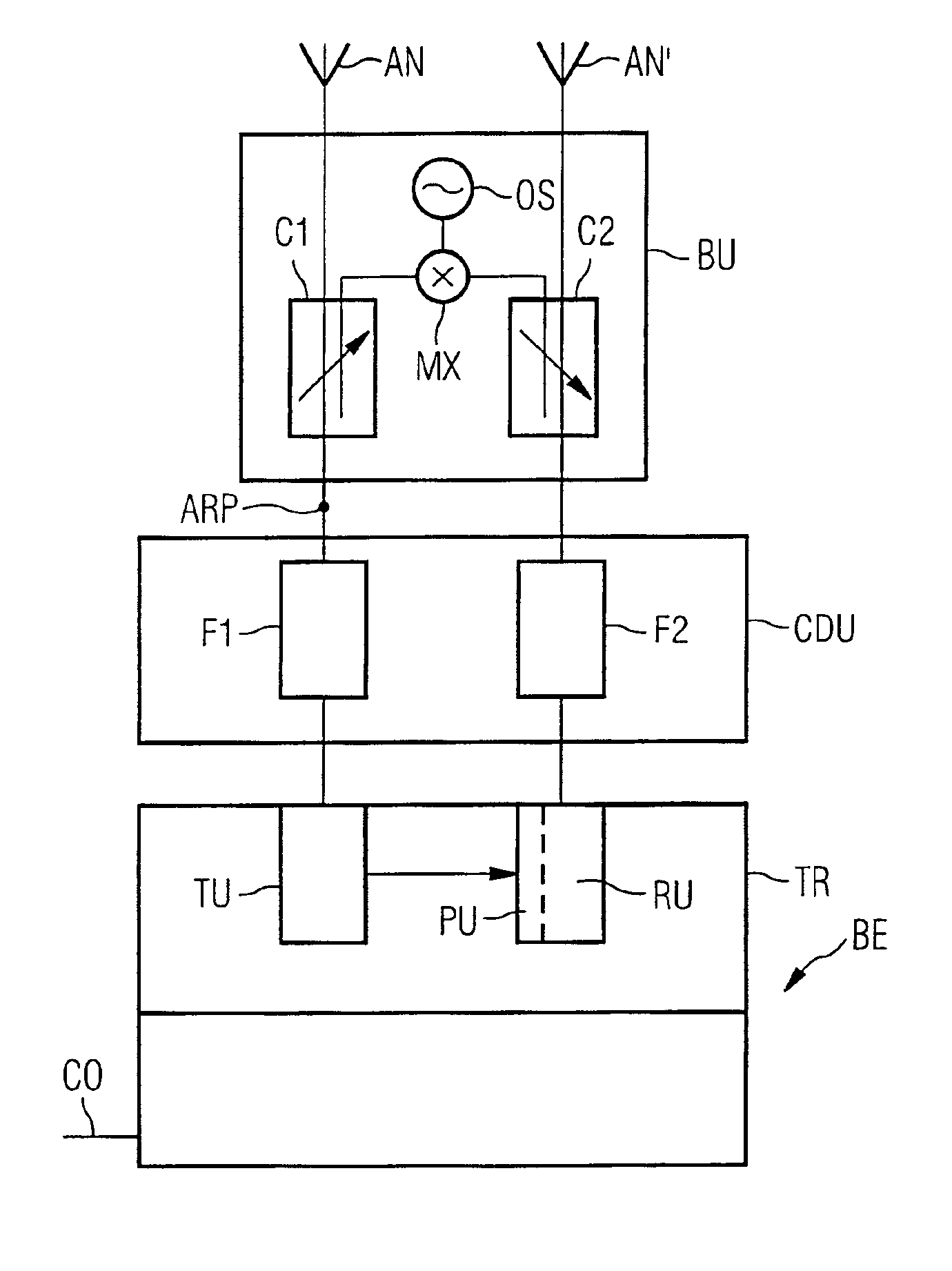
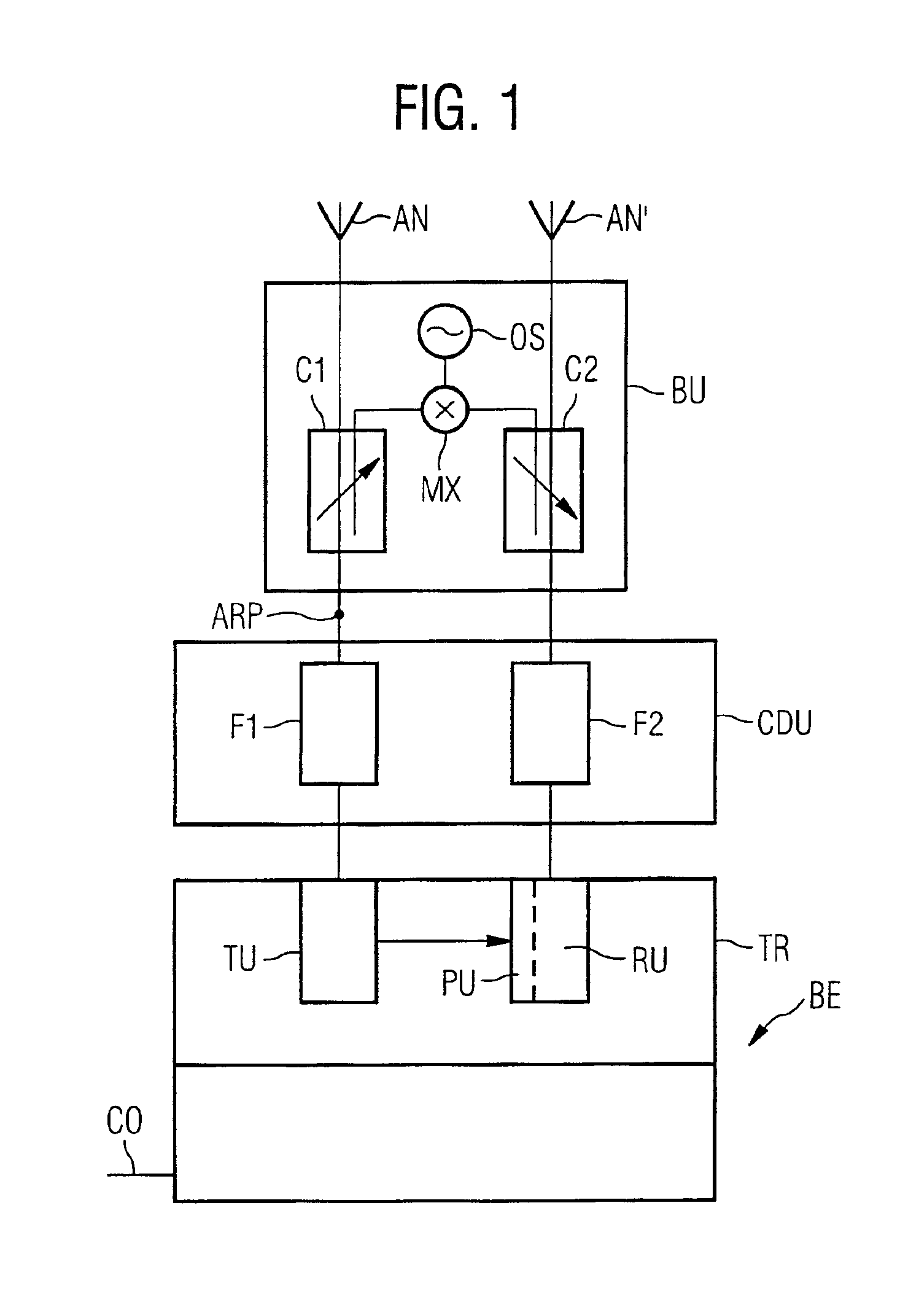
To reduce the interference between sent and received signals, the frequency ranges for transmission and reception of a base transceiver station are generally different with filters in the receive path blocking transmission bands and filters in the transmit path blocking reception bands. In a preferred embodiment, the branching unit comprises a converter for converting the frequency of the transferred signal to the input range of the receiver. If other methods are used to reduce interference between sent and received signals, e.g. a shift between transmission and reception in the time domain, the converter preferably performs a corresponding conversion, e.g. a signal delay with a delay element.
It is proposed that the converter comprises a mixer and an oscillator for a simple conversion of the signal frequency. The frequency of the oscillator is preferably half the difference in frequency between the transmission band and the reception band. The mixer mixes the signal generated by the oscillator and the signals transferred from the transmit path.
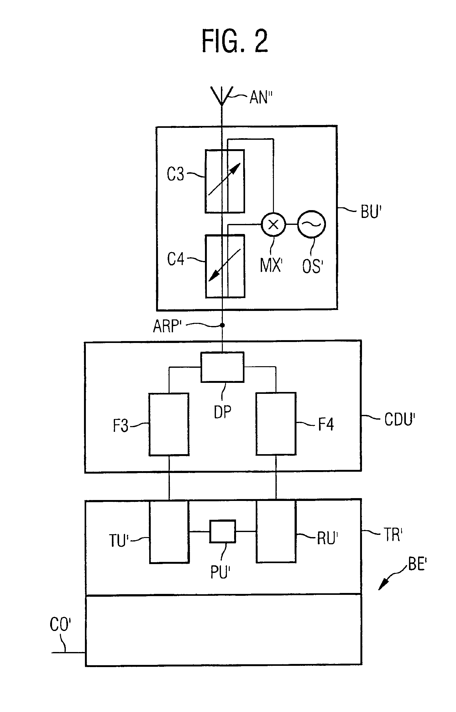
Often, the transmit path and the receive path have a common section. An advantageous branching unit branches the transmitted signal off from the common section and feeds the transferred signal back into the common section. This allows reduction of the length of connections required for the branching unit.
An advantageous branching unit is joined to the transmit path, the receive path or both with a coupler. The base transceiver station can in this way transmit during the measurements and the signal level can be adapted by the couplers to the value required at the receiver input. A switch and a corresponding control unit can be avoided for branching off the signals. Couplers can also be replaced by radio frequency switches. Especially for the connection of the branching unit to the receive path, a switch is often advantageous because disconnecting the antenna from the receiver avoids interference of the transferred signals and outside signals received over the antenna. A damping device in the branching unit can be used for adaptation of the signal level, especially if switches are used.

Problems solved by technology

Distortions which are acceptably small for a first transmission scheme, e.g. Gaussian minimum shift keying (GMSK) as used in GSM (Global System for Mobile Communication), may be too large for other modulation schemes.
The distortions in the transmit path of a base transceiver station can therefore become a problem if the transmitter of the base transceiver station is updated for another transmission scheme, e.g. to allow an increased data rate.
When a transmitter is upgraded and the base transceiver station has to observe stricter error vector requirements, correction values for already installed components may not be available while typical values for the respective type of component are not sufficiently exact.
If more than one component is part of the transmit path, e.g. a combining and distribution unit with filters and a tower mounted amplifier, it is difficult to obtain a compensation value which considers the influence of all components.
If a common compensation value is used for all frequencies of a transceiver, the correction can be insufficient for all or some of the frequencies.

Method used


Image

  • Base transceiver station with distortion compensation
  • Base transceiver station with distortion compensation
  • Base transceiver station with distortion compensation

Examples


Embodiment Construction

In FIG. 1, a base transceiver station according to the invention is depicted. The base transceiver station comprises a base station equipment BE with one or several transceivers TR. The base station equipment BE receives user data and control information from a further node in a communication system via a connection CO, e.g. from a base station controller (BSC) or a radio network controller (RNC) which connect the base transceiver station to a core network. The control information can for example comprise commands to change parameters used for radio signals like the frequency channels for transmission or reception of radio signals. The base station equipment BE controls the other components in the base transceiver station, especially the transceivers TR and a combining and distribution unit CDU. The combining and distribution unit CDU connects the transceivers TR to one or several antennas AN, AN′ for the emission and reception of radio signals.

Every transceiver TR comprises a trans...


PUM


Abstract

A base transceiver station for a radio communication system comprises a transmitter unit (TU), a receiver unit (RU) and a transmit path between the transmitter unit (TU) and an antenna. The receiver unit (RU) determines output data from received signals and the transmitter unit (TU) converts input data into transmitted signals and pre-distorts the transmitted signals using at least one compensation value. The base transceiver station comprises also a branching unit for transferring at least a portion of a transmitted signal from the transmit path to the receiver unit (RU) and a processing unit (PU) which is adapted to receive a representation of the input data and the output data. The processing unit (PU) compares the input data to the output data, determines a first compensation value for the pre-distortion according to the comparison and updates the compensation value of the transmitter unit (TU) with the first compensation value. Methods and computer programs embodying the invention are also described.

Description

BACKGROUND OF THE INVENTIONThe present invention relates to a base transceiver station provided with a transmitter unit, a receiver unit and a transmit path between the transmitter unit and an antenna, wherein the receiver unit determines output data from received signals and the transmitter unit converts input data into transmitted signals and pre-distorts the transmitted signals using at least one compensation value. Methods and software programs embodying the invention are also described.Base transceiver stations for radio communication systems provide wireless connections, e.g. to user equipment. A radio communication system can be for example a mobile communication system, a satellite communication system or a radio system for point to point transmissions. The base stations comprise at least one transmitter unit which is connected over a transmit path to an antenna or to an antenna system with several antennas. The transmitter unit converts input data, i.e. information bits, in...

Claims


Application Information

Patent Timeline
IPC IPC(8): H04B1/40H04B1/04H04L27/34H04L27/36
CPCH04B1/04H04L27/368H04B1/40
Inventor HILDEBRAND, UWEJECK, MICHAELUNSHELM, THOMAS
Owner TELEFON AB LM ERICSSON (PUBL)
Learn More