
Phase shifter with reduced linear dependency

a phase shifter and linear dependency technology, applied in the field of pseudorandom test vector generation, can solve the problems of increasing complexity of circuits, increasing logic-to-pin ratio, and high fault coverage of several types of fault models

Inactive Publication Date: 2005-03-29
SIEMENS PROD LIFECYCLE MANAGEMENT SOFTWARE INC
View PDF77 Cites 116 Cited by
  • Summary
  • Abstract
  • Description
  • Claims
  • Application Information

AI Technical Summary

Benefits of technology

The present invention provides a method for testing faults in integrated circuits using a linear finite state machine (LFSM) and a phase-shifter combination. The LFSM has a balanced load, meaning that each cell in the LFSM drives a similar number of logic gates in the phase-shifter. The LFSM cell outputs are selected by a pseudo-random number generator to ensure uniform distribution. The LFSM cells are also excluded from further generation if they have been used a similar number of times to prevent overlap with existing tap combinations. The invention also uses duality to determine if there are any elements produced by a linear combination of taps that belong to another sequence. The invention may be practiced using LFSMs exhibiting properties of characteristic polynomials that produce maximum-length sequences.

Problems solved by technology

However, as the complexity of circuits continues to increase, high fault coverage of several types of fault models becomes more difficult to achieve with traditional testing paradigms.
This difficulty arises for several reasons.
First, larger integrated circuits have a very high and still increasing logic-to-pin ratio that creates a test data transfer bottleneck at the chip pins.
Second, larger circuits require a prohibitively large volume of test data that must be then stored in external testing equipment.
Third, applying the test data to a large circuit requires an increasingly long test application time.
And fourth, present external testing equipment is unable to test such larger circuits at their speed of operation.
For large circuits, this approach becomes infeasible because of large test set sizes and long test application times. It has been reported that the volume of test data can exceed one kilobit per single logic gate in a large design.
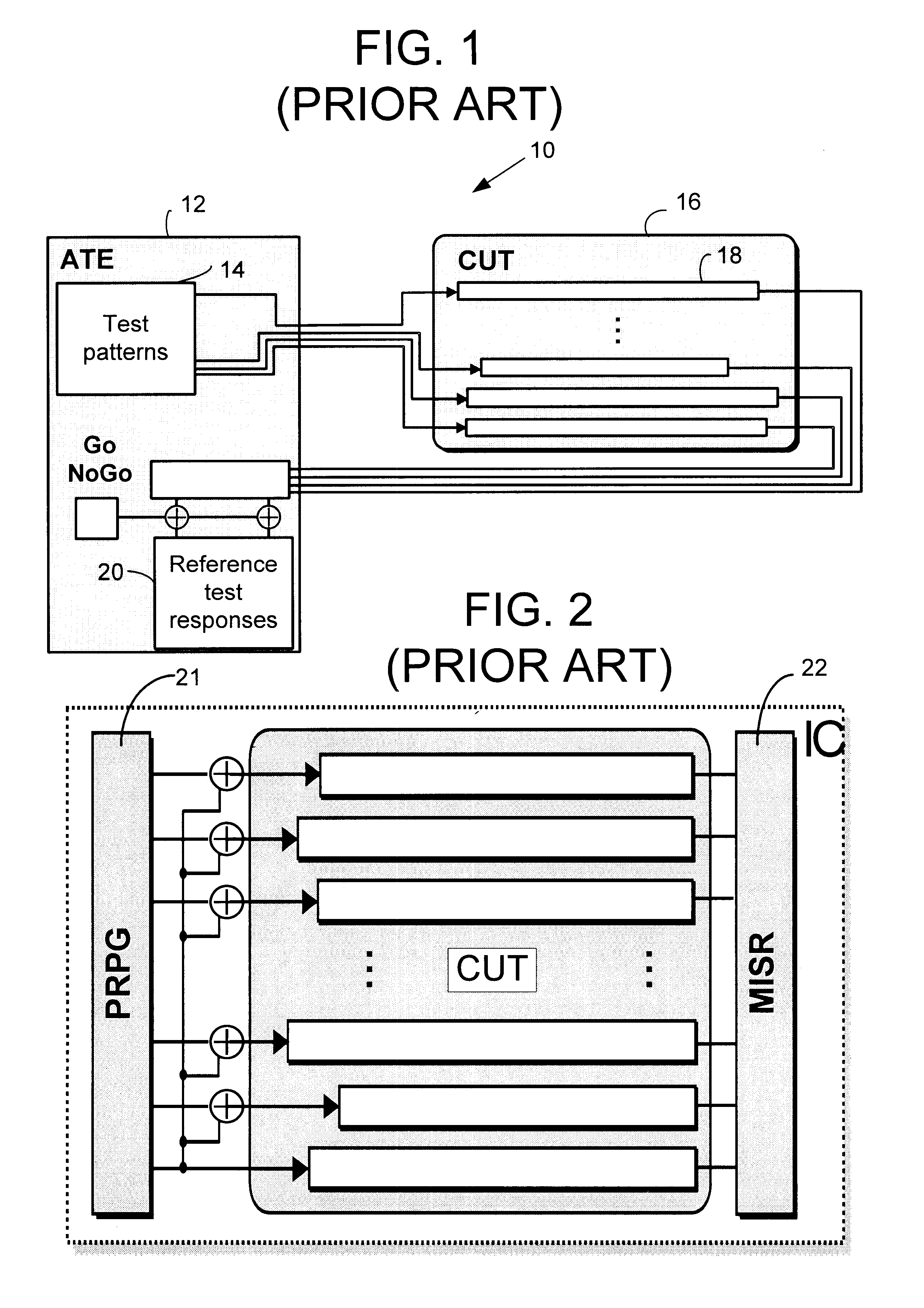
The significant limitation of this approach is that it requires an expensive, memory-intensive tester and a long test time to test a complex circuit.
Another limitation of BIST is that other types of faults, such as transition or path delay faults, are not handled efficiently by pseudo-random patterns.
Because of the complexity of the circuits and the limitations inherent in BIST, it is extremely difficult, if not impossible, to provide a set of test patterns that fully covers hard-to-test faults.
A problem with this design is that the resultant fault coverage is often unsatisfactory due to structural dependencies introduced by the LFSR.
This phenomenon can adversely affect fault coverage, as the patterns seen by the circuit under test (CUT) will not be pseudo-random.
The basic deficiencies of this approach are necessity to perform matrix operations and complexity of the resultant phase shifter which may feature, even after a decomposition and factorization process, an unnecessarily large number of XOR gates, and large propagation delays.
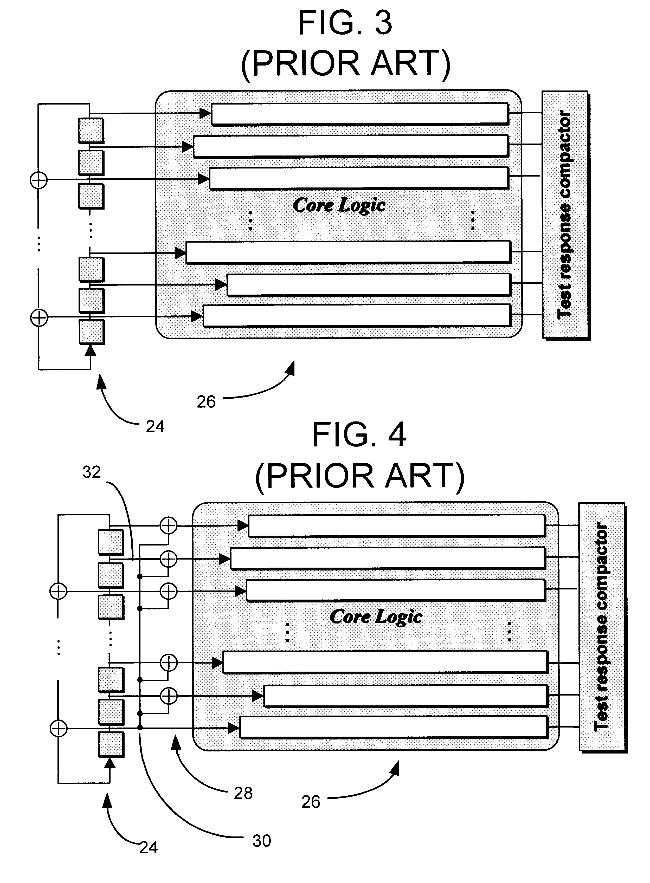
Such an excess loading increases capacitance resulting in slow signal propagation.
The discrepancy between loads on the taps of the LFSR increases linear dependency between the patterns stored in the scan chains.
Consequently, the separations between channels become variable, and complex calculations may be required to determine their actual values.
In addition, the solutions presented in that patent limits the number of output channels to the number of LFSR stages.
Unfortunately, the method used to design the variable-phase shifters is inherently ad hoc and becomes impractical for circuits with a large number of scan chains.
Unfortunately, the techniques described in these papers also have problems with load balancing.
Specifically, a discrepancy exists between loads on the LFSR taps that increases propagation delays and the linear dependency between the patterns stored in the scan chains.

Method used


Image

  • Phase shifter with reduced linear dependency
  • Phase shifter with reduced linear dependency
  • Phase shifter with reduced linear dependency

Examples


Embodiment Construction

Linear finite state machines (LFSMs), such as linear feedback shift registers (LFSRs) and cellular automata (CA), are often used for generating pseudo-random sequences. An example LFSM implements a characteristic primitive polynomial h(x)=hnxn+ . . . +h1x+h0 of degree n. Given this circuit, logic synthesis of phase shifters entails finding a set of linear combinations of the LFSM cell outputs such that each of the resulting sequences are shifted with respect to every other sequence by at least a pre-specified number of bits. Although a specific embodiment of the LFSM is described (i.e., a transformed LFSR), other LFSMs may be used. The transformed LFSR (also called the t-LFSR) includes memory elements in a ring structure with the feedback connections (in contrast to both type I and type II LFSRs) begin and terminate at different stages of the shift register, as shown in FIG. 5 for primitive polynomial x32+x18+x14+x9+1. For purposes of this description, the general form of LFSM shown...


PUM


Abstract

A method is disclosed for the automated synthesis of phase shifters. Phase shifters comprise circuits used to remove effects of structural dependencies featured by pseudo-random test pattern generators driving parallel scan chains. Using a concept of duality, the method relates the logical states of linear feedback shift registers (LFSRs) and circuits spacing their inputs to each of the output channels. The method generates a phase shifter network balancing the loads of successive stages of LFSRs and satisfying criteria of reduced linear dependency, channel separation and circuit complexity.

Description

TECHNICAL FIELDThis invention relates generally to generation of pseudo-random test vectors by means of linear feedback shift registers in multiple scan designs, and more particularly relates to means and methods for varying the phase shift and reducing linear dependency between test sequences occurring on the outputs-of parallel test pattern generators.BACKGROUNDAs integrated circuits are produced with greater and greater levels of circuit density, efficient testing schemes that guarantee very high fault coverage while minimizing test costs and chip area overhead have become essential. However, as the complexity of circuits continues to increase, high fault coverage of several types of fault models becomes more difficult to achieve with traditional testing paradigms. This difficulty arises for several reasons. First, larger integrated circuits have a very high and still increasing logic-to-pin ratio that creates a test data transfer bottleneck at the chip pins. Second, larger circu...

Claims


Application Information

Patent Timeline
Patent Type & Authority Patents(United States)
IPC IPC(8): G01R31/28G01R31/3181G01R31/3185G01R31/3183
CPCG01R31/31813G01R31/318385G01R31/318594G01R31/318547G01R31/318541
Inventor RAJSKI, JANUSZTYSZER, JERZYTAMARAPALLI, NAGESH
Owner SIEMENS PROD LIFECYCLE MANAGEMENT SOFTWARE INC
Learn More