Controller for the electric motor of a high-speed spindle attachment used with computer-controlled milling machines

Inactive Publication Date: 2005-04-05
NOELLE JOHN A +1
View PDF15 Cites 18 Cited by
  • Summary
  • Abstract
  • Description
  • Claims
  • Application Information

AI Technical Summary

Benefits of technology

It is the primary object of this invention to provide protection against the risk of catastrophic damage to the spindles of high-speed milling and grinding attachments used with computer-controlled milling machines when sudden power requirements occur during use beyond the level provided by the power supply and beyond the survivability of the electric motors associated with the attachments to utilize. This is accomplished in the present invention by having the electronic controller of the high-speed spindle attachment sense the power level being used by the electric motor associated with the attachment, and send a signal back to the computer controlling the axes of the cnc milling machine to slow, pause, and/or stop the feed-rate of the machining process should the power level in the electric motor exceed an operator-selected predetermined amount. One communication option between the electronic controller and the milling machine computer would be to have a

Problems solved by technology

One not readily apparent problem inherent in such systems, is the potential for catastrophic damage to the spindle due to sudden power requirements beyond the level provided by the power supply and beyond the survivability of the motor to utilize.
These sudden power requirements can occur unexpectedly when milling machine axes are under cnc control.
The inherent problem stems from the fact that small high-power electric motors derive their power primarily from speed rather than torque.
If the load imposed upon the motor exceeds the level for which it has been safely designed, the spindle will begin to slow down thereby increasing the chip load per tooth of the cutting

Method used


Image

  • Controller for the electric motor of a high-speed spindle attachment used with computer-controlled milling machines
  • Controller for the electric motor of a high-speed spindle attachment used with computer-controlled milling machines

Examples


Embodiment Construction

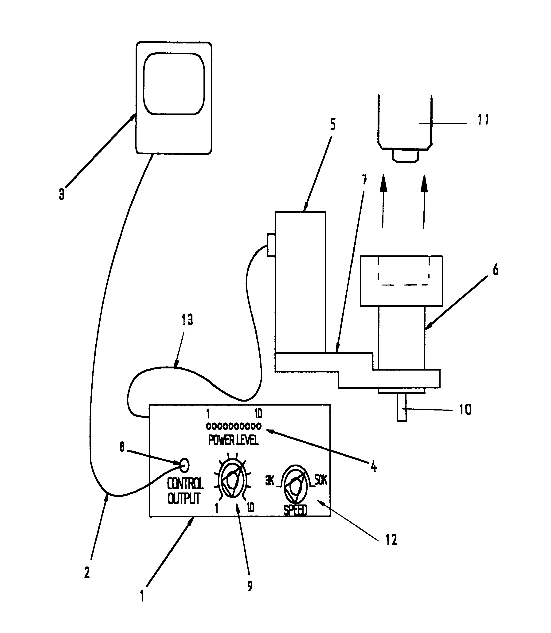
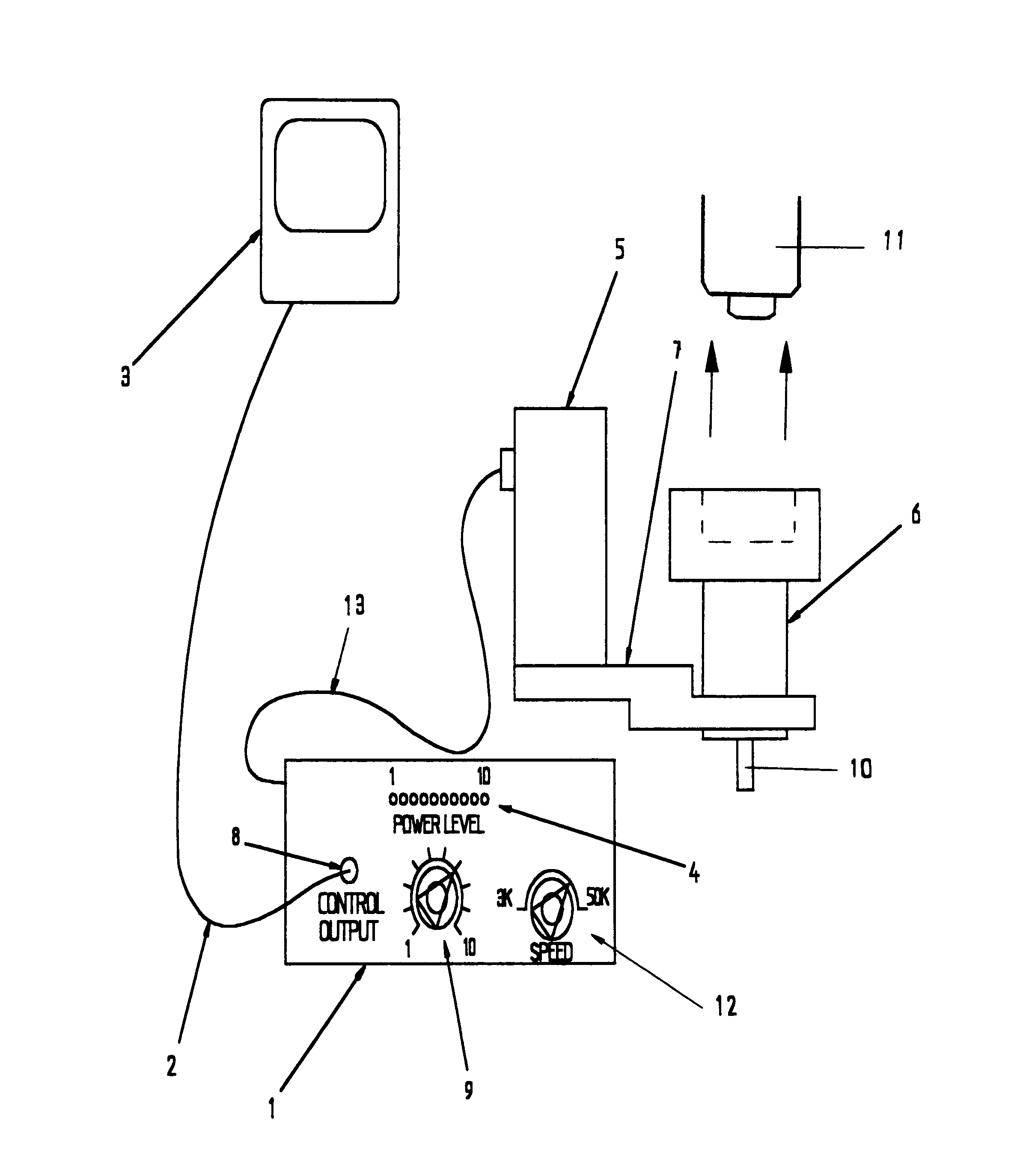
The most preferred embodiment of the controller improvement in the present invention is shown in the sole illustration provided. It consists of an electronic controller 1 having a variable speed control 12, a power level display 4, a multi-position switch 9 for operator-selectable threshold power level control, and a panel mounted bnc type connector 8, labeled “CONTROL OUTPUT”, at the control output of electronic controller 1. It is contemplated in the most preferred embodiment of the present invention for connector 8 to be adapted the connection of a bnc cable 2. As a result, the sole illustration shows electronic controller 1 being connected via electronic wiring 13 to the motor 5 of a high-speed spindle attachment 6 and via a bnc cable 2 to computer 3. However, other effective and efficient communication means between electronic controller 1 and computer 3 are also considered to be within the scope of the present invention, such as an analog signal. Communication between computer...


PUM

PropertyMeasurementUnit
Poweraaaaaaaaaa
Speedaaaaaaaaaa
Power consumptionaaaaaaaaaa

Abstract

An improved electronic controller for the motor of a high-speed spindle attachment used in conjunction with a cnc milling machine. The controller comprises preventative circuitry that protects the spindle assembly of the attachment from overload accruing as a result of relatively moderate increases in torque demand during use. The controller senses the power level being used by the motor while it causes high-speed spindle rotation, and when it identifies a power consumption rate by the spindle that exceeds the operator pre-set maximum level determined to be safe for avoiding catastrophic spindle damage, the electronic controller sends a signal back to the computer controlling the axes of the cnc milling machine that is sufficient to slow, pause, and/or stop the feed-rate.

Description

CROSS-REFERENCE TO RELATED APPLICATIONS None BACKGROUND OF THE INVENTION 1. Field of the Invention This invention relates to improvements in controllers for the electric motors of high-speed spindle attachments used with computer-controlled cnc milling machines, wherein such high-speed spindle attachments allow sustained spindle speeds up to and including speeds above 20,000 rpm in milling machines otherwise capable without attachments of only achieving maximum sustained spindle speeds of approximately 5000 rpm or less. 2. Description of the Related Art A high-speed spindle attachment for milling machines otherwise having a sustained maximum spindle speed of approximately 5,000 rpm, can be made compact and efficient by utilizing a high-speed electric motor controlled by an electronic controller designed to maintain a constant speed even under widely varying loads, such as described in U.S. Pat. No. 5,878,476 to Noelle (1999). One not readily apparent problem inherent in such systems...

Claims


Application Information

Patent Timeline
IPC IPC(8): B23F1/00B23C1/00G06F19/00B23Q5/10B23Q5/58
CPCB23Q5/10B23Q5/58Y10T409/307448Y10T408/165Y10T409/306664Y10T409/303752Y10T409/308176Y10T408/14
Inventor NOELLE, JOHN ANOELLE, THOMAS J
Owner NOELLE JOHN A
Why Eureka
Try Eureka