
Particle filter for microelectromechanical systems

Inactive Publication Date: 2005-04-05
NEOPHOTONICS CORP
View PDF7 Cites 11 Cited by
  • Summary
  • Abstract
  • Description
  • Claims
  • Application Information

AI Technical Summary

Benefits of technology

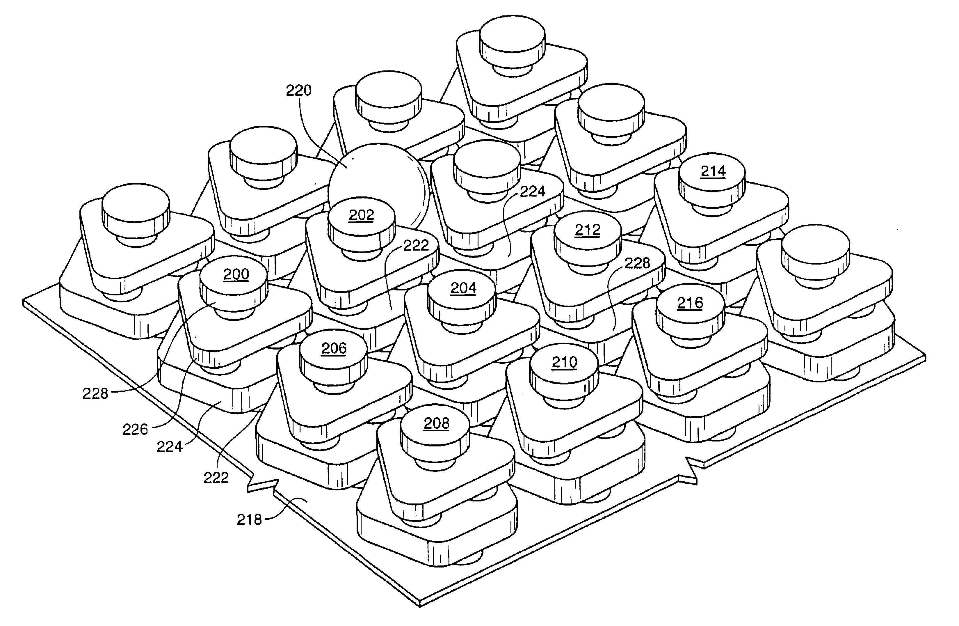
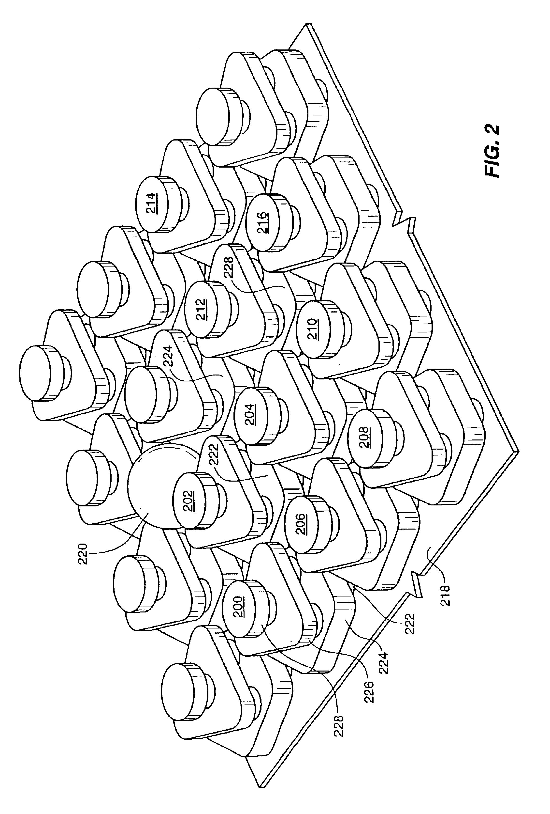
Various refinements exist of the features noted in relation to the subject microelectromechanical system. Further features may also be incorporated into the system to form multiple examples of the present invention. These refinements and additional features will be apparent from the following description and may exist individually or in any combination. For instance, a plurality of particle traps each including arrays of geometric structures may be included in the microelectromechanical system in the areas void of the micro-devices. Advantageously, the plurality of particle traps provide a more uniform surface topography during manufacturing of a microelectromechanical system and thus help to prevent undesired characteristics such as “dishing” of the microdevices, which often occurs during chemical mechanical polishing steps of the fabrication process.

Problems solved by technology

Unfortunately, it is a problem in the art of microelectromechanical systems to prevent particle contamination.
Particle contamination can potentially ruin an entire system by interfering with the electrical signals and / or mechanical movements of some or all of the electrical and / or mechanical devices.
Furthermore, as will be appreciated, such particle contamination has a high likelihood of occurring in areas of the microelectromechanical system that have a high density of surface features, and thereby can potentially cause the most significant harm.

Method used


Image

  • Particle filter for microelectromechanical systems
  • Particle filter for microelectromechanical systems
  • Particle filter for microelectromechanical systems

Examples


Embodiment Construction

Reference will now be made to the accompanying drawings, which at least assist in illustrating the various pertinent features of the present invention. For purposes of illustration, the following description is related to the formation of particle filters for microelectromechanical (MEM) systems, although it will be appreciated that the present particle filter is easily formed and useful for both micromechanical and microelectromechanical systems. In addition, one or more micro-devices or microstructures may define any given micromechanical or microelectromechanical system.

Surface micromachining is the preferred type of technique for fabricating the particle filter described herein, although other techniques may be utilized as well. Moreover, in certain instances it may be desirable to use a combination of two or more fabrication techniques to define a given MEM system. Since surface micromachining is the preferred fabrication technique for the particle filter and MEM systems descri...


PUM

PropertyMeasurementUnit
Structureaaaaaaaaaa
Shapeaaaaaaaaaa

Abstract

A particle filter for microelectromechanical systems is provided that includes a particle trap formed on a substrate material. The particle trap includes an array of multidimensional geometric structures in an adjacent relationship. The geometric structures further define a plurality of multidimensional voids therebetween for trapping particles therein. The individual multidimensional geometric structures are formed by a plurality of vertically interconnected geometric shapes to define different configurations of voids between the adjacent geometric structures. In one embodiment of the filter system, an electrical bias is applied to the array of multidimensional geometric structures to facilitate attracting and trapping of particles in the filter.

Description

FIELD OF THE INVENTIONThe invention is related to the field of microelectromechanical systems, and in particular, to a particle filter that prevents particulate contamination of the micro-electrical and / or micro-mechanical devices that make up these systems.BACKGROUND OF THE INVENTIONMicroelectromechanical systems include highly miniaturized devices that employ electrical and / or mechanical components. These systems are typically fabricated using integrated circuit batch-processing techniques. There are a number of fabrication technologies, collectively known as micromachining, for producing microelectromechanical systems. One type of micromachining process is surface micromachining. Surface micromachining involves deposition and photolithographic patterning of alternate layers of structural material (typically polycrystalline silicone, termed polysilicon) and sacrificial layers (typically silicon dioxide, termed oxide) on a silicon wafer substrate material. Using a series of deposit...

Claims


Application Information

Patent Timeline
IPC IPC(8): B81B7/00
CPCB81B7/0012Y10T428/12674
Inventor RODGERS, MURRAY STEVEN
Owner NEOPHOTONICS CORP
Learn More