Organic electroluminescent device having host material layer intermixed with luminescent material

a luminescent material and electroluminescent technology, applied in thermoelectric devices, discharge tubes luminescnet screens, natural mineral layered products, etc., can solve the problems of failure to achieve the objects of emitted white light or continuous full color light, structure employed can only cast monochromatic lights according to various chosen fluorescent materials,

Inactive Publication Date: 2005-04-05
PENG KUAN CHANG
View PDF4 Cites 47 Cited by
  • Summary
  • Abstract
  • Description
  • Claims
  • Application Information

AI Technical Summary

Benefits of technology

[0018]It is the primary object of the present invention to provide an organic electroluminescent device, characterized in that optimal light distribution of light densities of three different frequency bands is achieved to realize continuous white / full color light.
[0019]It is another object of the present invention to provide a method for manufacturing an organic electroluminescent device, so as to overcome the afore-mentioned problems in manufacturing a white / full color display.
[0020]It is still another object of the present invention to provide an organic electroluminescent device and a method for manufacturing the same, incorporating host material layers and guest luminescent materials so as to enhance the luminescence efficiency and to prolong the lifetime.

Problems solved by technology

However, the structure employed can only cast monochromatic lights according to various chosen fluorescent materials, and fail to achieve the objects of emitting white light or continuous full color light.
1. Color conversion: In this method, a monochromatic light passes through a color conversion material composed of different color conversion layers and is then resolved and converted into light with different colors, e.g. three primary colors, such as red, blue, and green so that an organic EL device capable of emitting white light or full color light can be obtained. However, this method also suffers from a number of problems.
First, for example, most of the available color conversion materials are not satisfactory in color purity and luminescence efficiency.
Secondly, the background light (such as blue light and UV light) may also be absorbed by the color conversion layers, which often leads to poor contrast and defective pixel quality.
2. Color filter: In this method, white light is used as the back-lighting source of the organic EL material. It is useful to achieve full color light when accompanied by LCD color filters. However, the key problem of this method is how to obtain a reliable white light.
3. Three independent colors (RBG): In this method, three primary colors red (R), green (G) and blue (B) are independently demonstrated to realize a full color display or a white light source. However, since the three colors are independently demonstrated, RBG pixels require different driving voltages. It suffers from complicated fabrication process and larger size. In addition, in such a device, high precision is critically required for the RBG pixels. It is found that the fabrication process may be difficult and complicated. On one hand, the RBG pixels formed of three different organic EL materials may have different luminescence efficiencies, lifetimes, driving conditions. For example, the red light shows poor purity and may shift to orange color. The red light also has shorter lifetime and may adversely affect the overall performance of the display. On the other hand, the method is performed by a two-wavelength approach; therefore, chromatic aberration may occur.

Method used


Image

  • Organic electroluminescent device having host material layer intermixed with luminescent material
  • Organic electroluminescent device having host material layer intermixed with luminescent material
  • Organic electroluminescent device having host material layer intermixed with luminescent material

Examples


Embodiment Construction

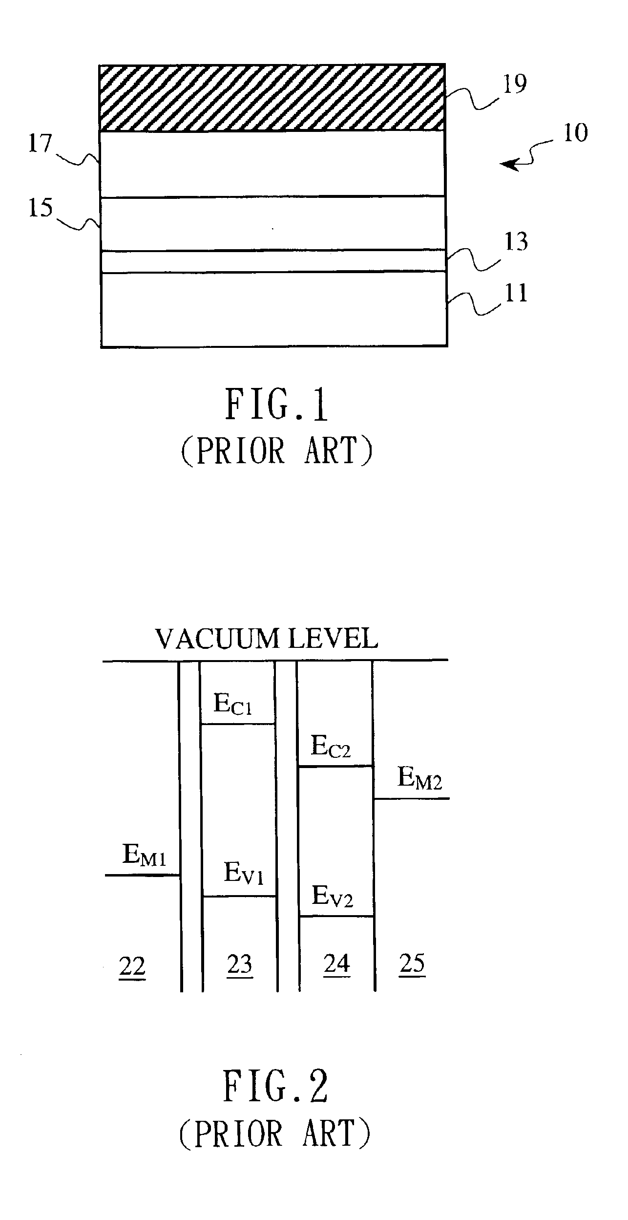
ss="d_n">[0025]FIG. 1 is a cross-sectional view showing the structure of an organic EL device in accordance with the prior art;

[0026]FIG. 2 is a schematic band diagram showing the structure of another organic EL device in accordance with the prior art;

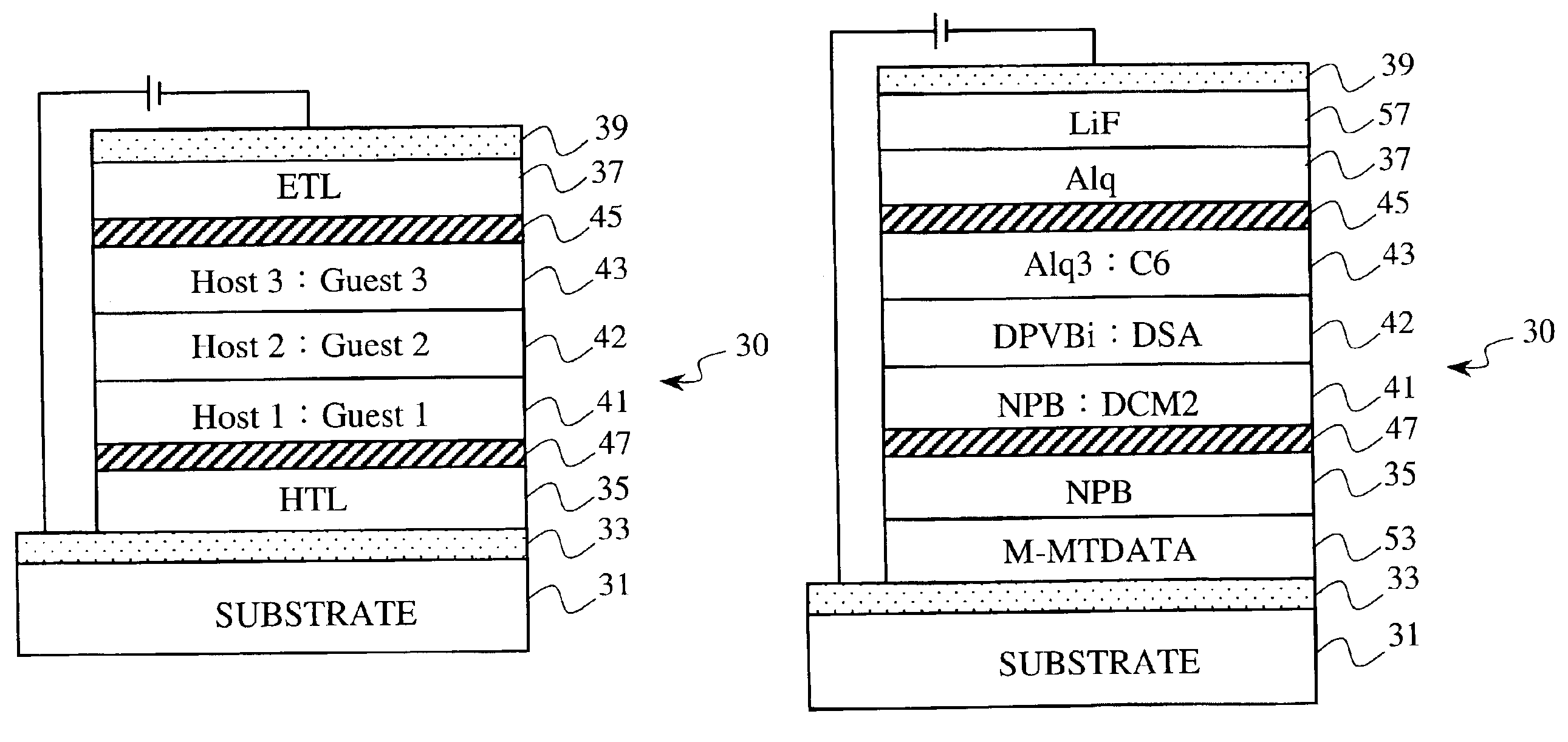
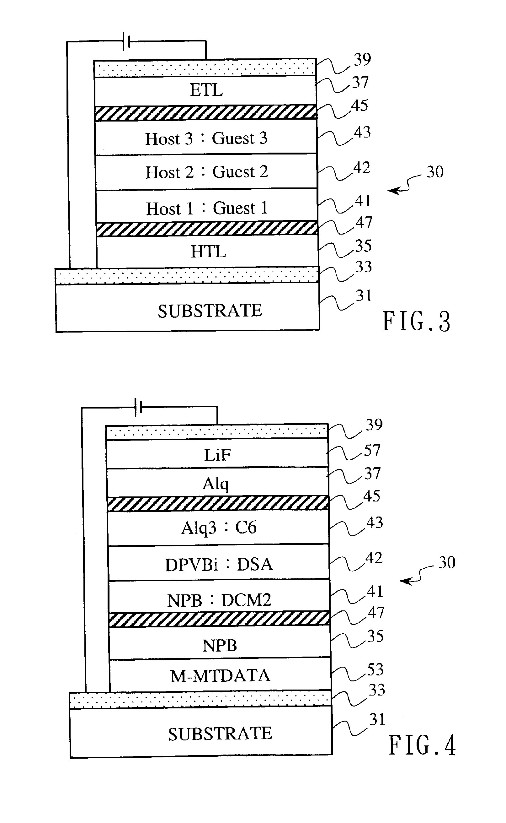
[0027]FIG. 3 is a cross-sectional view showing the structure of an organic EL device in accordance with one preferred embodiment of the present invention; and

[0028]FIG. 4 is a cross-sectional view showing the structure of an organic EL device in accordance with another preferred embodiment of the present invention.

DETAILED DESCRIPTION OF THE INVENTION

[0029]The present invention providing an organic light-emitting device and a method for manufacturing the same can be exemplified by the preferred embodiments as described hereinafter.

[0030]To start with, please refer to FIG. 3, which is a cross-sectional view showing the structure of an organic EL device in accordance with one preferred embodiment of the present invention. As shown in the...


PUM

PropertyMeasurementUnit
organicaaaaaaaaaa
bias voltageaaaaaaaaaa
luminescentaaaaaaaaaa

Abstract

The present invention discloses a white light emitting organic electroluminescent (EL) device able to directly emit continuous full color light containing three different frequency bands and a method for manufacturing such an organic electroluminescent device. The device comprises: a first conductive layer having a first conductive type; a first carrier transmission layer; a second carrier blocking layer; a first host material layer formed on the first conductive layer, wherein the first host material layer is doped with a first guest luminescent material so as to cast a first color light source under a bias voltage; a second host material layer formed on the first host material layer, wherein the second host material layer is doped with a second guest luminescent material so as to cast a second color light source under the bias voltage; a third host material layer formed on the second host material layer, wherein the third host material layer is doped with a third guest luminescent material so as to cast a third color light source under the bias voltage; a first carrier blocking layer; a second carrier transmission layer; and a second conductive layer having a second conductive type formed on the third host material layer.

Description

BACKGROUND OF THE INVENTION[0002]1. Field of the Invention[0003]The present invention generally relates to an organic light-emitting device (also known as OLED) and a method for manufacturing the same and, more particularly, to a white light emitting organic electroluminescent (EL) device able to directly cast continuous full color light containing three different frequency bands and a method for manufacturing such an organic electroluminescent device.[0004]2. Description of the Prior Art[0005]The organic electroluminescent device, upon which C. W. Tang and S. A. Van Slyke (Eastman Kodak Company, Rochester, N.Y.) have made efforts since 1987 so as to deposit hole / electron transmission materials such as aluminum trisoxine [a.k.a., tris (8-quinolinol) aluminum] by vacuum evaporation on an indium-tin oxide (ITO) glass followed by the deposition of a metal electrode, has attracted tremendous attention due to its advantages over other display panels. These advantages include self-lumines...

Claims


Application Information

Patent Timeline
Patent Type & Authority Patents(United States)
IPC IPC(8): H05B33/14H05B33/20H05B33/12H01L51/05H01L51/30H01L51/00H01L51/50
CPCH05B33/20H01L51/5096H05B33/14H01L51/5036H01L51/0059H01L51/0062H01L51/0081H10K85/649H10K85/631H10K85/324H10K50/125H10K50/18
Inventor PENG, KUAN-CHANG
Owner PENG KUAN CHANG
Why Eureka
Try Eureka