Driving circuit for organic electroluminescence device

a driving circuit and electroluminescence technology, applied in the direction of electric variable regulation, process and machine control, instruments, etc., can solve the problems of difficulty in using the driving circuit, miniaturization and low cost limitations,

Inactive Publication Date: 2005-04-05
LG ELECTRONICS INC
View PDF5 Cites 47 Cited by
  • Summary
  • Abstract
  • Description
  • Claims
  • Application Information

AI Technical Summary

Benefits of technology

Preferably, the driving circuit for an organic EL display device further includes a power peripheral unit provided outside the chip, for controlling input and output v

Problems solved by technology

Since ICs for power supply, sold in the market, are separately used, several limitations according to miniaturization and low cost

Method used


Image

  • Driving circuit for organic electroluminescence device
  • Driving circuit for organic electroluminescence device
  • Driving circuit for organic electroluminescence device

Examples


Embodiment Construction

Reference will now be made in detail to the preferred embodiments of the present invention, examples of which are illustrated in the accompanying drawings.

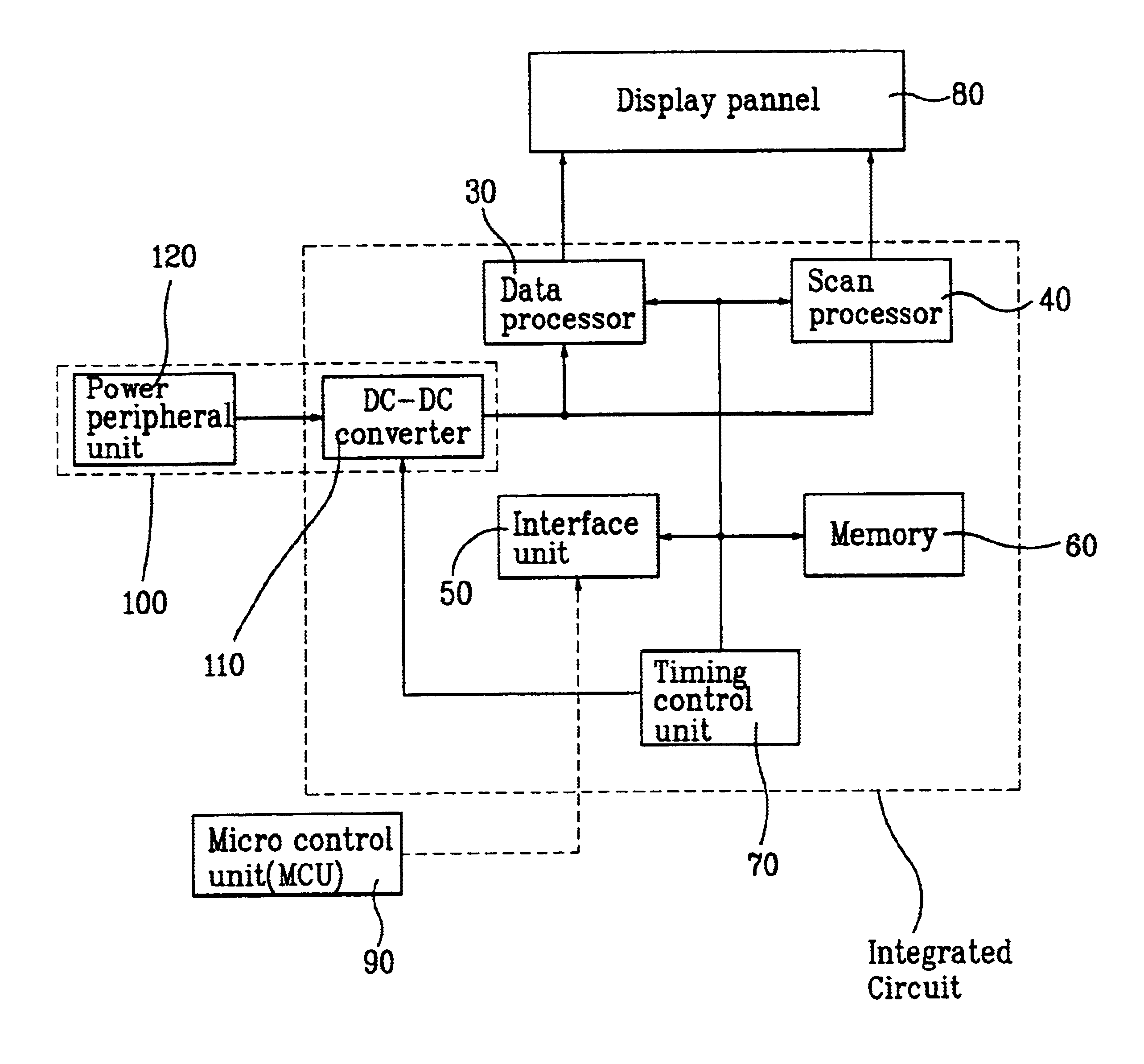
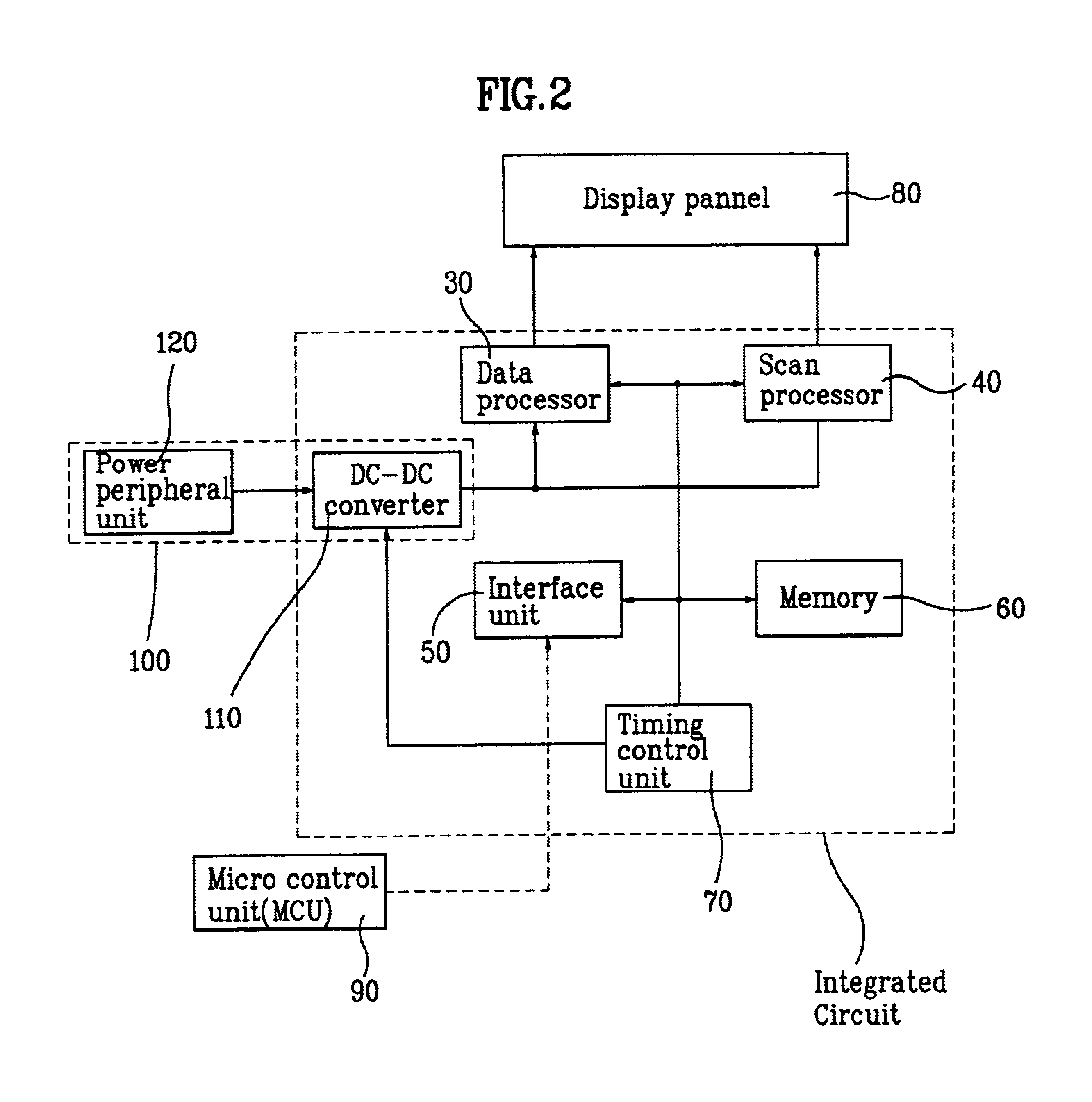
FIG. 2 is a block diagram illustrating a structure of a driving circuit for an organic EL device in accordance with the present invention.

Referring to FIG. 2, the driving circuit includes a data processor 30, a scan processor 40, an interface unit 50, a memory 60, a timing control unit 70, and a DC-DC converter 110.

The DC-DC converter 110 is provided inside the driving circuit which is an IC.

Also, the DC-DC converter 110 controls a DC voltage externally provided by timing control signals and provides the controlled DC voltage to the other components inside the driving circuit.

The interface unit 50 interfaces the components of the driving circuit with am external MCU located outside the driving circuit.

The memory 60 stores display information transmitted through the interface unit 50.

The data processor 30 outputs a display data for...


PUM


Abstract

A driving circuit of electroluminescence (EL) display device is disclosed, which is divided into an integrated circuit (IC) and an exterior circuit. The IC includes a DC-DC converter for controlling an external DC voltage to a desired DC voltage through a timing control signal. A power peripheral unit is provided outside the IC, which controls an input voltage and an output voltage of the DC-DC converter and stabilizes the DC-DC converter. The DC-DC converter generates a desired DC voltage using the external input voltage according to a voltage control signal subject to the timing control signal. The generated DC voltage is provided to a data processor and a scan processor inside the IC. It is possible to control the DC voltage inside the IC using the DC-DC converter controlled by the timing control signal, and most parts of a power portion can be integrated inside the IC.

Description

BACKGROUND OF THE INVENTION1. Field of the InventionThe present invention relates to a driving circuit of a display device, and more particularly, to a driving circuit of an organic electroluminescence (EL) device using a DC-DC converter.2. Background of the Related ArtRecently, a flat display market is rapidly developing.A flat display, developed beginning with liquid crystal displays (LCD), has received much attention. A cathode ray tube (CRT), which had been generally used in the field of display for several decades, is recently being replaced with flat displays such as Plasma Display Panel (PDP), Visual Fluorescent Display (VFD), Field Emission Display (FED), Light Emitting Diode (LED), and Electro-luminescence (EL).With development or the flat display, many studies for decreasing a size of Integrated Circuits (IC) used in the flat display and decreasing the number of external parts are in progress.A power supply is separately formed outside the ICs without being formed inside t...

Claims


Application Information

Patent Timeline
IPC IPC(8): G09G3/32G09G3/30H02J1/06H02M3/155
CPCG09G3/3208H02J1/06H02M3/155G09G2330/02G09G3/30
Inventor KIM, HAK SU
Owner LG ELECTRONICS INC
Why Eureka
Try Eureka