Diffraction grating device

a grating device and grating technology, applied in the direction of instruments, optical waveguide light guides, optical light guides, etc., can solve the problems of large radiation mode loss and transmission loss generated by optical coupling, and achieve the effects of shortening longitudinal length, efficient reflection, and increasing index modulation amplitud

Inactive Publication Date: 2005-04-05
SUMITOMO ELECTRIC IND LTD
View PDF3 Cites 41 Cited by
  • Summary
  • Abstract
  • Description
  • Claims
  • Application Information

AI Technical Summary

Benefits of technology

To efficiently reflect light containing a number of reflection wavelengths, the diffraction grating device must shorten the longitudinal length of each of the plurality of regions in which index modulations are formed and also increase the amplitude of index modulations in each of the plurality of regions. However, if the amplitude of index modulations in each of the plurality of regions is large, light radiation from the core region to the cladding region increases, ...

Problems solved by technology

However, if the amplitude of index modulations in each of the plurality of regions is large, light radiation from the core region to the cladding region increases, resulting in a large radiation mode l...

Method used


Image

  • Diffraction grating device
  • Diffraction grating device
  • Diffraction grating device

Examples


Embodiment Construction

The embodiment of the present invention will be described below in detail with reference to the accompanying drawings. The same reference numerals denote the same elements throughout the drawings, and a repetitive description thereof will be omitted. For the descriptive convenience, orthogonal coordinate systems are illustrated in the figures.

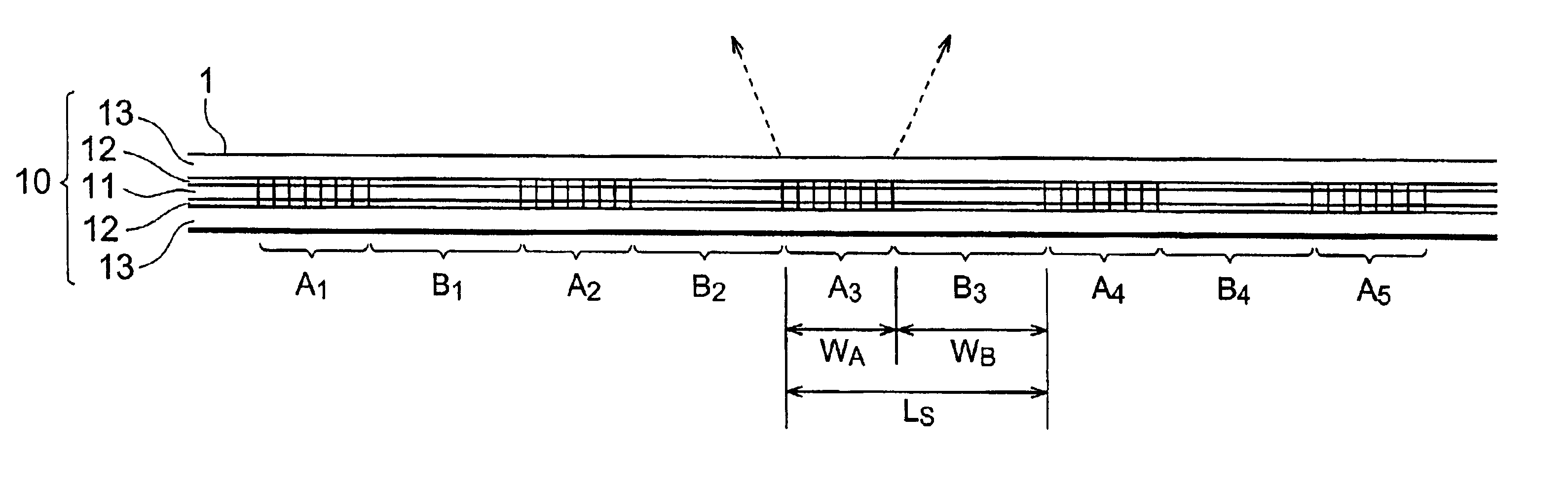
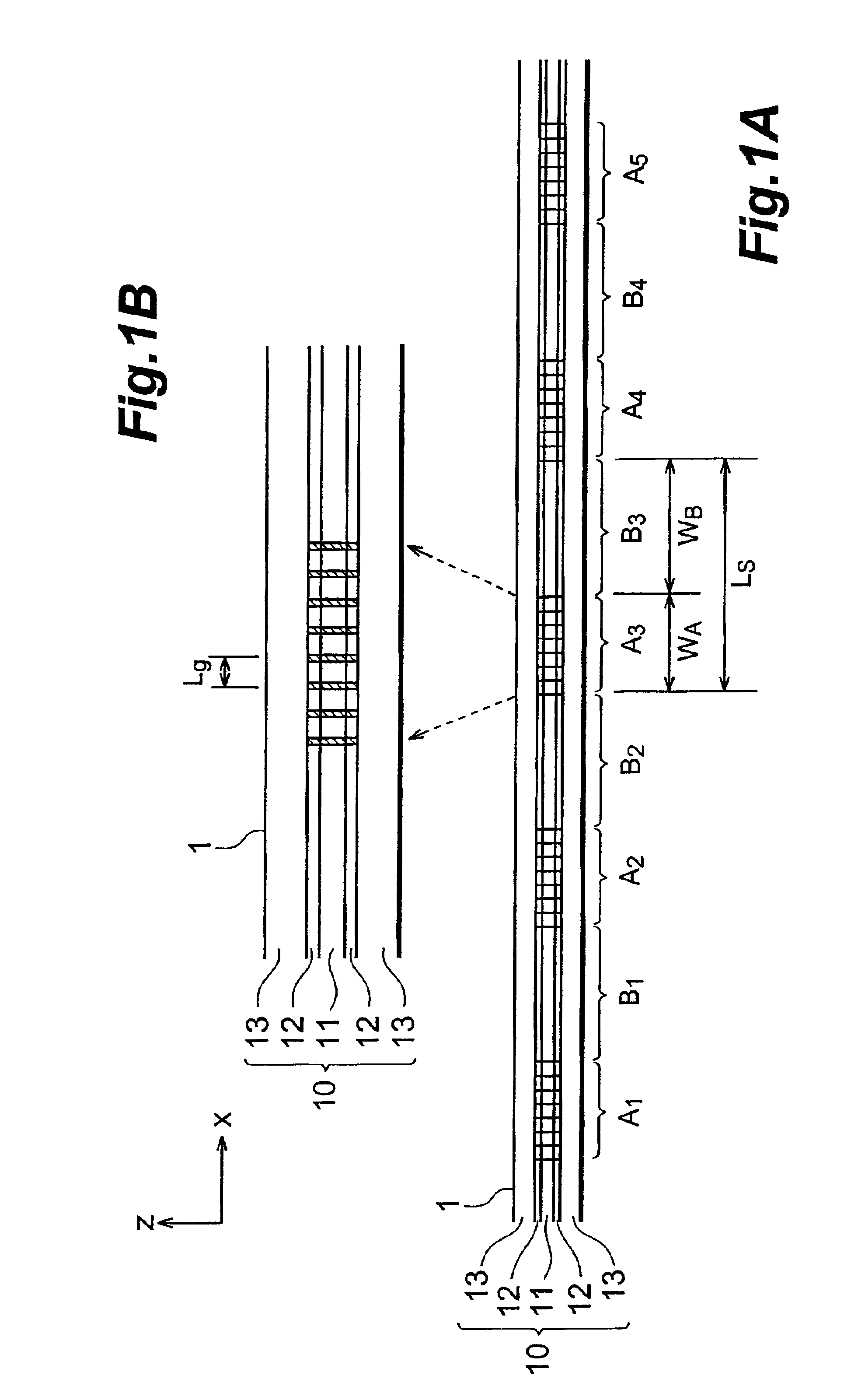
FIG. 1A is a sectional view of a diffraction grating device 1 according to this embodiment. FIG. 1B is an enlarged view of part of FIG. 1A. FIG. 1A shows a section of the diffraction grating device 1 taken along a plane including the optical axis of the diffraction grating device 1.

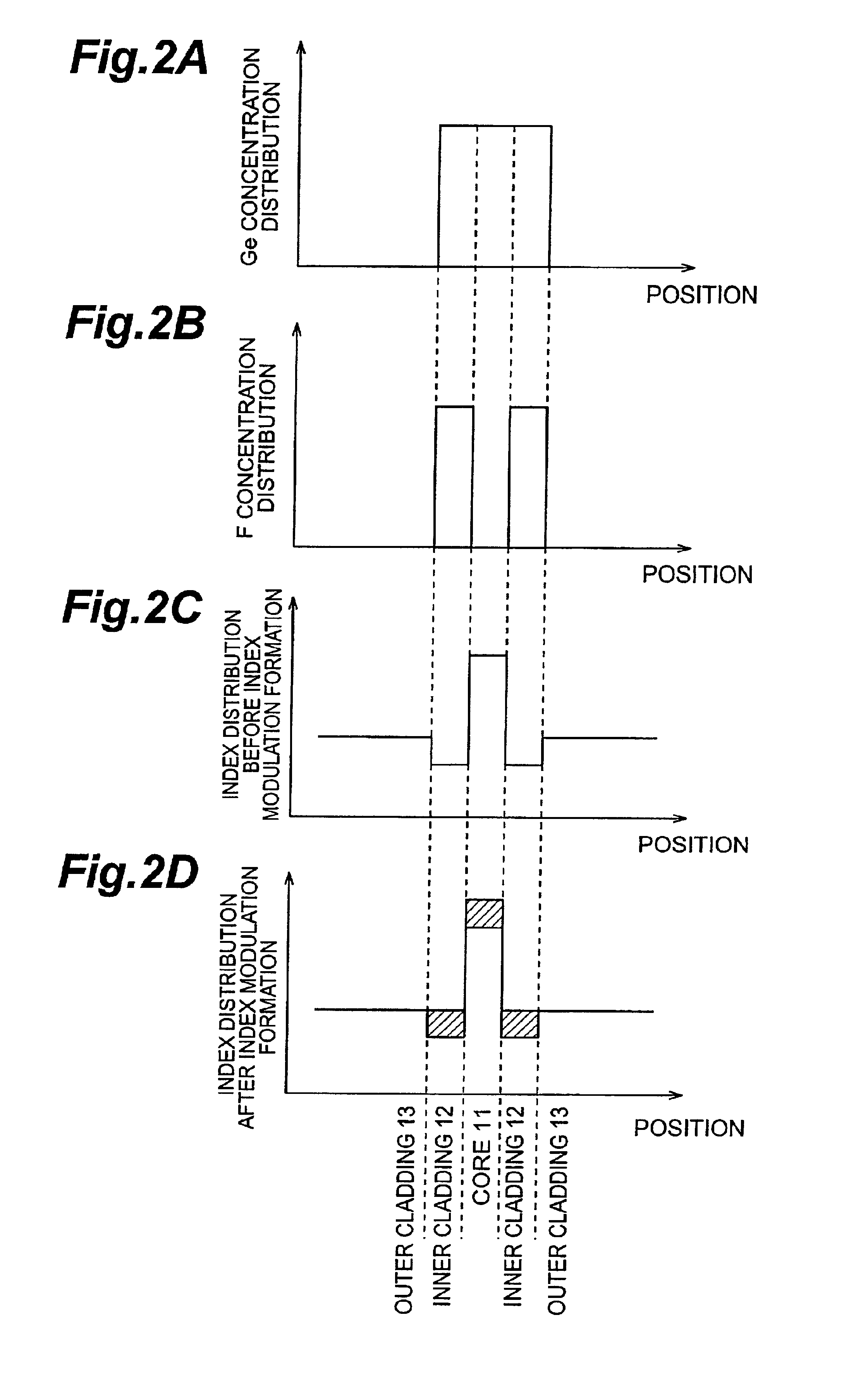
In the diffraction grating device 1, index modulations are formed along the longitudinal direction (X-axis direction) of an optical fiber 10 serving as an optical waveguide. The optical fiber 10 has a core region 11, inner cladding region 12, and outer cladding region 13 sequentially from the optical axis center. Index modulations are formed in both the core region 1...


PUM


Abstract

In a diffraction grating device (1), index modulations are formed along the longitudinal direction of an optical fiber (10) serving as an optical waveguide. The optical fiber (10) has a core region (11), an inner cladding region (12), and an outer cladding region (13) sequentially from the optical axis center. Index modulations are formed in both the core region (11) and the inner cladding region (12) of the optical fiber (10) in each of a plurality of regions A1 to AN (N is an integer; N≧2) separated from each other along the longitudinal direction of the optical fiber (10). In the diffraction grating device (1), regions An (n=1 to N) in which index modulations are formed in both the core region (11) and the inner cladding region (12) and regions Bn (n=1 to N−1) in which no index modulations are formed alternately exist along the longitudinal direction.

Description

BACKGROUND OF THE INVENTION1. Field of the InventionThe present invention relates to a diffraction grating device in which index modulations are formed along the longitudinal direction of an optical waveguide.2. Related Background ArtA diffraction grating device has index modulations formed in the longitudinal direction of an optical waveguide (optical fiber or planar optical waveguide). Especially, a diffraction grating device in which Bragg type index modulations are formed can selectively reflect, out of guided light components, a light component having a specific wavelength that satisfies the Bragg condition, and is therefore used as an optical filter or the like in an optical communication system. Such a diffraction grating device is manufactured by the two-beam interference method or phase grating method. In such a diffraction grating device, normally, index modulations having a predetermined period are formed in one region along the longitudinal direction of an optical wavegu...

Claims


Application Information

Patent Timeline
IPC IPC(8): G02B6/124G02B6/12G02B6/02
CPCG02B6/02085G02B6/021G02B6/12007G02B6/124G02B6/02138G02B2006/12107
Inventor MURASHIMA, KIYOTAKAHASHIMOTO, KENIWASHIMA, TORU
Owner SUMITOMO ELECTRIC IND LTD
Why Eureka
Try Eureka