Fluid diffusion resistant glass-encased optical sensor

a technology of optical sensors and diffusion protection mechanisms, which is applied in the direction of optical radiation measurement, force measurement by measuring optical property variation, instruments, etc., can solve the problems of poor signal to noise ratio, sensitivity and accuracy of fiber optic sensors, and often harsh environments for sensors, etc., to achieve enhanced force to wavelength shift sensitivity, low hysteresis, and easy scalable for the desired sensitivity

Inactive Publication Date: 2005-04-12
WEATHERFORD TECH HLDG LLC
View PDF51 Cites 9 Cited by
  • Summary
  • Abstract
  • Description
  • Claims
  • Application Information

AI Technical Summary

Benefits of technology

[0012]The present invention also provides a fluid blocking fiber optic pressure sensor having a fiber grating encased in and fused to at least a portion of a sensing element, such as a capillary tube, which is elastically deformable when subject to applied pressure. The invention substantially eliminates' drift, and other problems, associated with water or other fluid absorption into the tube. The tube may be made of a glass material for encasing a glass fiber. The invention provides low hysteresis. Furthermore, one or more gratings, fiber lasers, or a plurality of fibers may be encased in the coated tube. The grating(s) or reflective elements are “encased” in the tube b

Problems solved by technology

Such sensors may often be subjected to extremely harsh environments, such as temperatures up to 200 degrees C. and pressures up to 20 kpsi.
However, the sensitivity and accuracy of fiber optic sensors creates problems when such sensors are used in a harsh environment.
Known problems include poor signal to noise ratios, wavelength drift, wavelength shifts, optical losses, hysteresis and mechanical reliability issues.
One such known problem is “creep” of the sensor over time.
It has been discovered that the attachment of the sensing element to the elastic structure can be a large source of error if the attachment is not highly stable.
A major source of such long-term sensor instability is creep, i.e., a change in strain on the sensing element even with no change in applied load on the elastic structure, which results in a DC shift or drift error in the sensor signal.
In addition, the senso

Method used


Image

  • Fluid diffusion resistant glass-encased optical sensor
  • Fluid diffusion resistant glass-encased optical sensor
  • Fluid diffusion resistant glass-encased optical sensor

Examples


Embodiment Construction

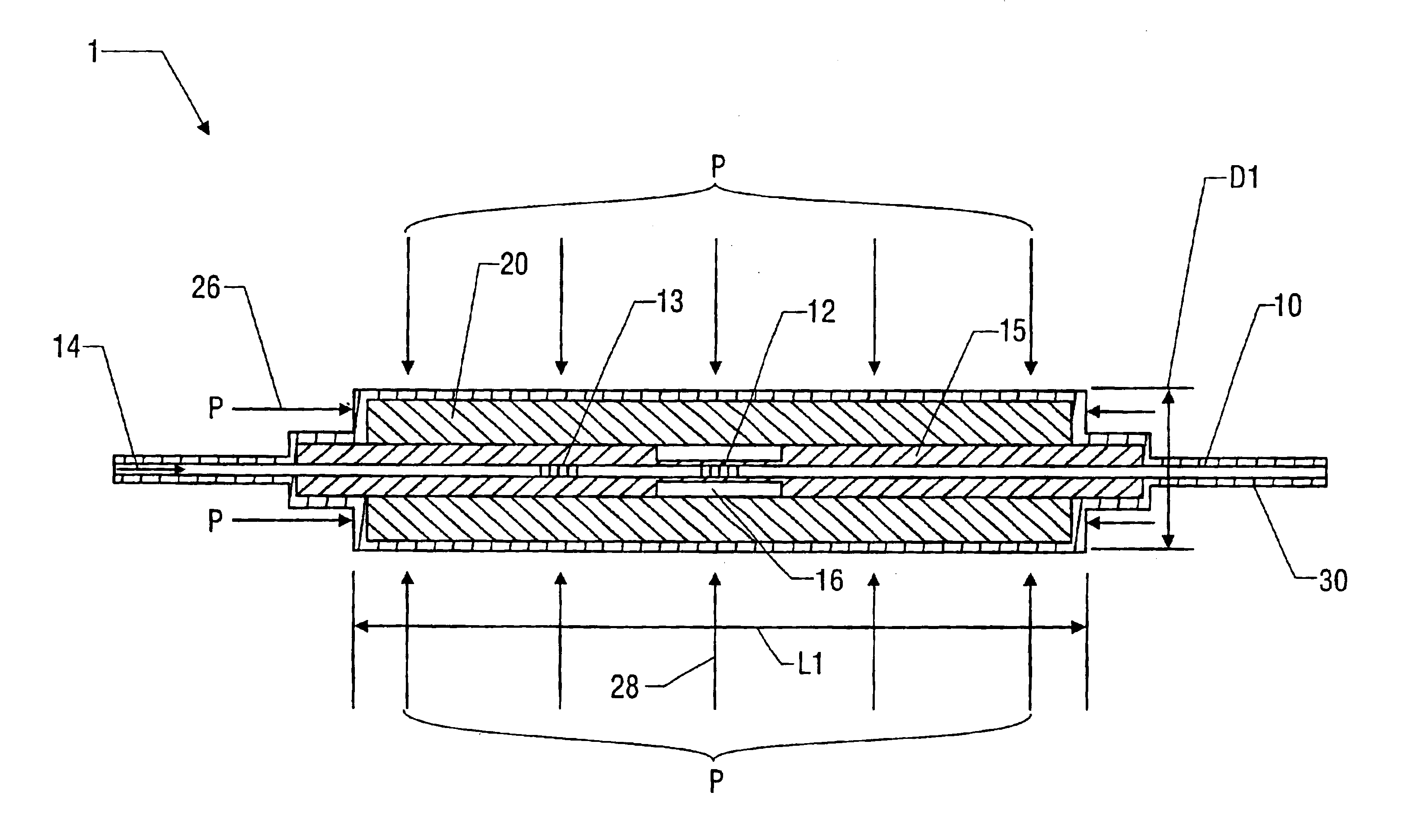
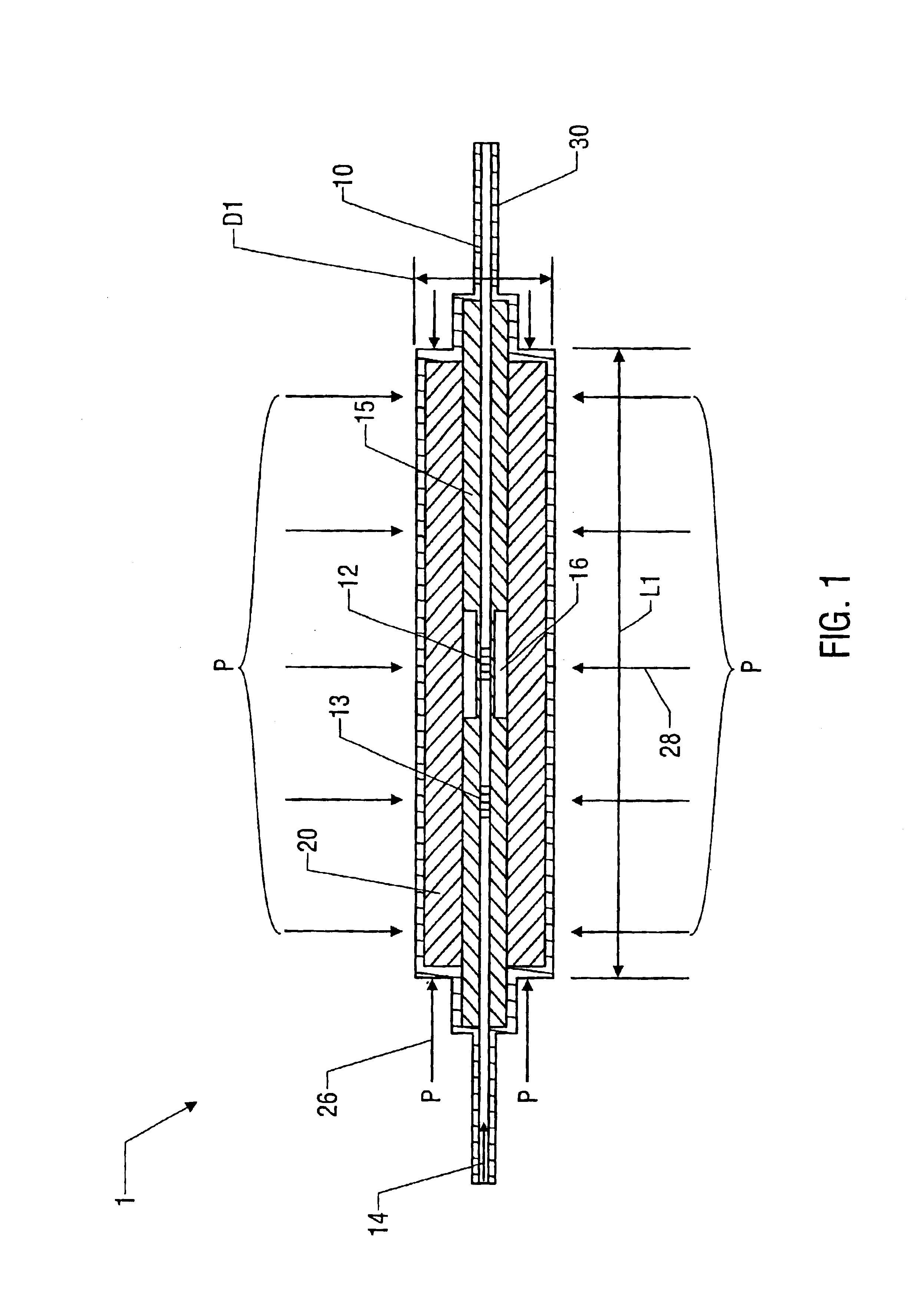
[0019]Referring to FIG. 1, a tube-encased fiber Bragg grating transducer 1 comprises a known optical waveguide 10, e.g., a standard telecommunication single mode optical fiber, having a pressure Bragg grating 12 and a temperature Bragg grating 13 impressed (or embedded or imprinted) in the fiber 10. The fiber 10 is encased within shell 20 such as is described in copending U.S. patent application Ser. Nos. 09 / 455,867, entitled “Bragg Grating Pressure Sensor,” filed Dec. 6, 1999, and Ser. No. 09 / 455,865, entitled “Tube-Encased Fiber Grating,” also filed Dec. 6, 1999, both of which are hereby incorporated by reference in their entirety.

[0020]In one embodiment, the transducer element 1 is constructed by fusing a bare photosensitive fiber 10 in a fused silica capillary tube 15, which functions as a piston as will be described herein below. In the embodiment shown in FIG. 1, Bragg grating 12 is approximately 5 mm in length (although other lengths are possible) and is disposed in the “dogb...


PUM


Abstract

A fluid diffusion resistant tube-encased fiber grating pressure sensor includes an optical fiber 10 having a Bragg grating 12 impressed therein which is encased within a sensing element, such as a glass capillary shell 20. A fluid blocking coating 30 is disposed on the outside surface of the capillary shell to prevent the diffusion of fluids, such as water molecules from diffusing into the shell. The fluid diffusion resistant fiber optic sensor reduces errors caused by the diffusion of water into the shell when the sensor is exposed to harsh conditions.

Description

CROSS REFERENCES TO RELATED APPLICATIONS[0002]This application is a continuation of U.S. patent application Ser. No. 09 / 494,417, filed Jan. 31, 2000, now U.S. Pat. No. 6,626,043, which is incorporated herein by reference and to which priority is claimed under 35 U.S.C. § 120.[0003]This application is also related to: U.S. patent application Ser. No. 09 / 399,404, filed Sep. 20, 1999, which is a continuation-in-part of U.S. patent application Ser. No. 09 / 205,944, filed Dec. 4, 1998, Ser. No. 09 / 455,865, entitled “Tube-Encased Fiber Grating,” Ser. No. 09 / 455,866, entitled “Strain-Isolated Bragg Grating Temperature Sensor,” U.S. Pat. No. 6,229,827, entitled “Compression-Tuned Bragg Grating and Laser,” Ser. No. 09 / 456,113, entitled “Pressure Isolated Bragg Grating Temperature Sensor,” U.S. Pat. No. 6,278,811, entitled “Fiber Optic Bragg Grating Pressure Sensor,” Ser. No. 09 / 455,868, entitled “Large Diameter Optical Waveguide, Grating, and Laser,” and U.S. Pat. No. 6,298,184, entitled “Met...

Claims


Application Information

Patent Timeline
IPC IPC(8): G01L1/24G01L9/00G01L11/02
CPCG01L1/246G01L9/0077G01L11/025
Inventor BAILEY, TIMOTHY J.FERNALD, MARK R.KERSEY, ALAN D.MACDOUGALL, TREVOR W.PUTNAM, MARTIN A.
Owner WEATHERFORD TECH HLDG LLC
Why Eureka
Try Eureka