
Fuel processor apparatus and method based on autothermal cyclic reforming

Inactive Publication Date: 2005-04-12
GENERAL ELECTRIC CO
View PDF4 Cites 25 Cited by
  • Summary
  • Abstract
  • Description
  • Claims
  • Application Information

AI Technical Summary

Benefits of technology

The present invention provides fuel processing methods and systems based on the autothermal cyclic reforming process, for the generation of a hydrogen-rich stream from fossil fuels and bio-fuels. In one illustrative embodiment, the fuel processor generates a hydrogen-rich gas stream for use in stationary fuel cells. Another illustrative embodiment provides a method and system for producing high-purity hydrogen for use in hydrogen vehicle refueling and industrial hydrogen applications. The methods and systems as disclosed in exemplary embodiments of the present invention integrate various components of the fuel processor in a unique manner that result in systems with increased efficiency and lower capital costs over prior art approaches.
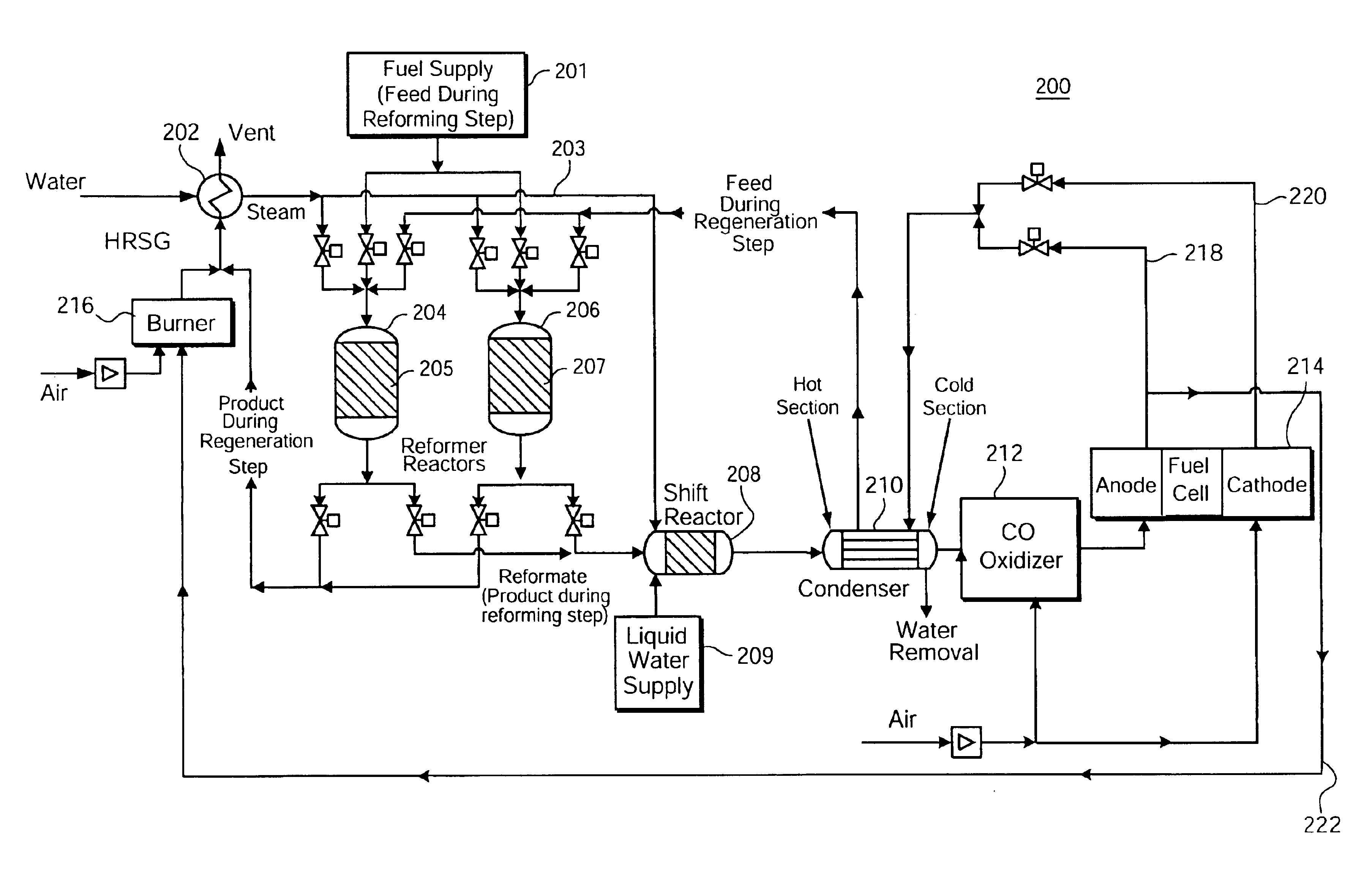
The anode and cathode vent streams are preferably passed through the condenser before being received by the reformer reactor in the regeneration step. The anode and cathode vent streams are mixed, or cycled alternately, or a combination thereof. The remainder of the anode vent stream is provided to an auxiliary burner associated with the HRSG to produce additional heat to generate steam. The auxiliary burner is also supplied with air for enabling the HRSG to generate steam. Each integrated heat exchanger enables transfer of heat from a product gas output by respective reformer reactor to a feed gas to the respective reformer reactor. The integrated heat exchanger preferably reduces the temperature of the product gas from about 700-1000 degrees C. to about 200-700 degrees C., thereby recovering heat from the product gas.
Another exemplary aspect of the present invention provides a fuel processor based on autothermal cyclic reforming process for generating a hydrogen-rich gas, the apparatus including two reformer reactors with integrated heat exchangers, the two reformer reactors cycling between a reforming step and a regeneration step. A heat recovery steam generator (HRSG) is provided for generating steam which is mixed with fresh fuel, and the mixture is delivered to the reformer reactor in the reforming step to produce a hydrogen-rich reformate gas. A shift reactor is provided for receiving the reformate gas to reduce the concentration of carbon monoxide (CO) gas present in the reformate gas. A condenser is provided for receiving the shift reactor product gas to recover heat from the shift reactor product gas. A CO oxidizer is provided for receiving output gas stream from the condenser to further reduce the concentration of the CO in the condenser output gas stream. Also provided in the apparatus is a fuel cell having anode and cathode sections, the anode section receiving gas stream output by the CO oxidizer, and the cathode section receiving ambient air.
The fuel processor also includes an auxiliary burner associated with the HRSG, the burner receiving the remainder of the anode vent stream to produce additional heat to generate steam. The integrated heat exchanger reduces the temperature of the product gas from about 700-1000 degrees C. to about 200-700 degrees C., thereby recovering heat from the product gas. The shift reactor reduces the concentration of CO in the reformate stream to less than 2%.
In a further exemplary and non-limiting aspect, the present invention provides in a fuel processor based on autothermal cyclic reforming process, the processor having two reformer reactors with integrated heat exchangers, the two reactors cycling between a reforming step and a regeneration step, a method of generating hydrogen including receiving a mixture of fuel and steam in the reformer reactor operating in a reforming step to produce a hydrogen-rich reformate gas. The reformate gas is fed to a shift reactor to reduce the concentration of carbon monoxide (CO) gas present in the reformate. A CO oxidizer is interposed between a first and second heat exchangers, each of the first and second heat exchangers including a hot section and a cold section. Product gas generated by the shift reactor is received in the hot section of the first heat exchanger for recovering heat, and output gas stream from the first heat exchanger is delivered to the CO oxidizer to reduce the concentration of CO.

Problems solved by technology

Although various processes have been developed for generating hydrogen-rich gas stream for use in such applications as fuel cells, hydrogen vehicle refueling, and industrial use, each has its own drawbacks.
These conditions are too severe for the use of reactor tubes made of mild steel or even stainless steel.
Furthermore, heat must be supplied since the reaction is highly endothermic.
Unfortunately, however, combustion is an “all or nothing” process.
Since the heat is not liberated uniformly throughout the reactor, there is again a severe heat transfer problem.
Heat transfer is also a substantial problem in other industrial processes in which packed bed reactors are used to carry out endothermic reactions.

Method used


Image

  • Fuel processor apparatus and method based on autothermal cyclic reforming
  • Fuel processor apparatus and method based on autothermal cyclic reforming
  • Fuel processor apparatus and method based on autothermal cyclic reforming

Examples


Embodiment Construction

The benefits of the present invention will become apparent to those skilled in the art from the following detailed description, wherein a preferred embodiment of the invention is shown and described, simply by way of illustration of the best mode contemplated of carrying out the invention.

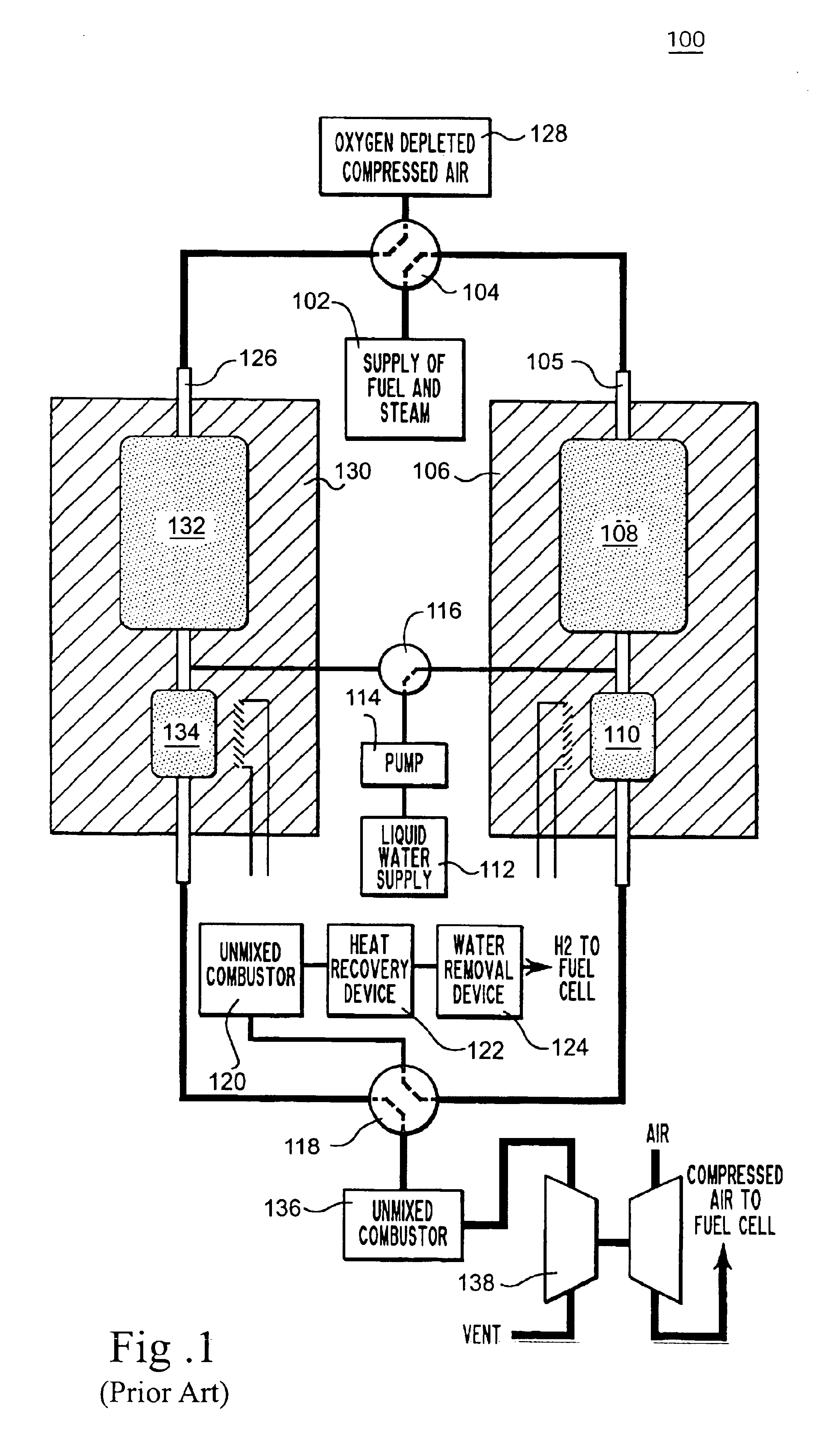
FIG. 1 shows a packed bed reactor system 100, using the ACR process, for producing a hydrogen-rich stream for use in fuel cells. The packed bed reactor system of FIG. 1 includes a supply 102 provides a flowing stream of steam and a liquid or gaseous hydrocarbon at a pressure greater than about 60 psig to a four-way valve 104. The four-way valve directs this flowing gas stream into the top of a reactor 105. Reactor 105 is covered with insulation 106 and has a main section 108 and a smaller section 110. Both main section 108 and smaller section 110 contain a mixture of two catalysts.

Conditions are adjusted so that the temperature in a main section 108 is in a range from about 600° C. to about 800° C....


PUM

PropertyMeasurementUnit
Fractionaaaaaaaaaa
Temperatureaaaaaaaaaa
Concentrationaaaaaaaaaa

Abstract

In a fuel processor based on autothermal cyclic reforming process, the fuel processor having a reformer, the reformer having two reactors with integrated heat exchangers, the two reactors cycling between a reforming step and a regeneration step, a method of generating hydrogen gas includes receiving a mixture of fuel and steam in the reformer reactor operating in a reforming step to produce hydrogen-rich reformate gas. The fuel is delivered from a fuel supply and the steam is generated by a heat recovery steam generator (HRSG). The reformate gas is fed to a shift reactor to reduce the concentration of carbon monoxide (CO) gas present in the reformate gas. Product gas generated by the shift reactor is received in a condenser to recover heat from the product gas. In one embodiment output gas stream from the condenser is supplied to a CO oxidizer to further reduce the CO concentration. The output gas stream from the CO oxidizer is supplied to an anode of a fuel cell, the fuel cell including a cathode for receiving ambient air to initiate an electrochemical reaction with the gas stream received by the anode. In another embodiment the output gas stream from the condenser is supplied to a Pressure Swing Adsorber (PSA). The output gas is high-purity hydrogen which can be utilized for industrial hydrogen or hydrogen vehicle refueling applications.

Description

BACKGROUND OF THE INVENTIONThis invention generally relates to methods and systems for generation of a hydrogen-rich stream, and more particularly to a fuel processor apparatus and method for generating a hydrogen-rich gas stream based on the autothermal cyclic reforming (ACR) process.Fuel processors convert fossil fuels (such as natural gas and diesel fuel) or bio-fuels to either a hydrogen-rich gas for fuel cells or a pure hydrogen stream. The major subsystem of the fuel processor is the reformer. The reformer converts fuel to a reformate stream, which is a mixture of CO, CO2, H2, steam and hydrocarbons. The shift reactor is almost always used downstream of the reformer reactor. In the shift reactor, CO reacts with steam to produce H2 and CO2.If the hydrogen-rich gas needs to be processed by a Proton Exchange Membrane (PEM) fuel cell, a CO oxidizer is used downstream of the shift reactor. The CO oxidizer utilizes air to oxidize most of the remaining CO to CO2. If the hydrogen-rich...

Claims


Application Information

Patent Timeline
IPC IPC(8): C01B3/00C01B3/48H01M8/06
CPCC01B3/48H01M8/0612H01M8/0668Y02E60/50C01B2203/0283C01B2203/044C01B2203/047C01B2203/0495C01B2203/066C01B2203/0805C01B2203/0811C01B2203/0822C01B2203/0827C01B2203/0894C01B2203/141C01B2203/146C01B2203/0233Y02P20/10Y02P20/129
Inventor KUMAR, RAVI VIPPERLAKASTANAS, GEORGE N.
Owner GENERAL ELECTRIC CO
Learn More