
Hybrid magnetic/electrostatic deflector for ion implantation systems

a technology of ion implantation and magnetic field, which is applied in the field of hybrid magnetic/electrostatic deflector for ion implantation systems, can solve the problems of undesirable energy contamination at the workpiece, the ability of beam current to drop substantially, etc., and achieve the effect of uniform magnetic field, facilitating the neutralization of space charge, and reducing the impact of space charge effects

Active Publication Date: 2005-04-19
AXCELIS TECHNOLOGIES
View PDF19 Cites 38 Cited by
  • Summary
  • Abstract
  • Description
  • Claims
  • Application Information

AI Technical Summary

Benefits of technology

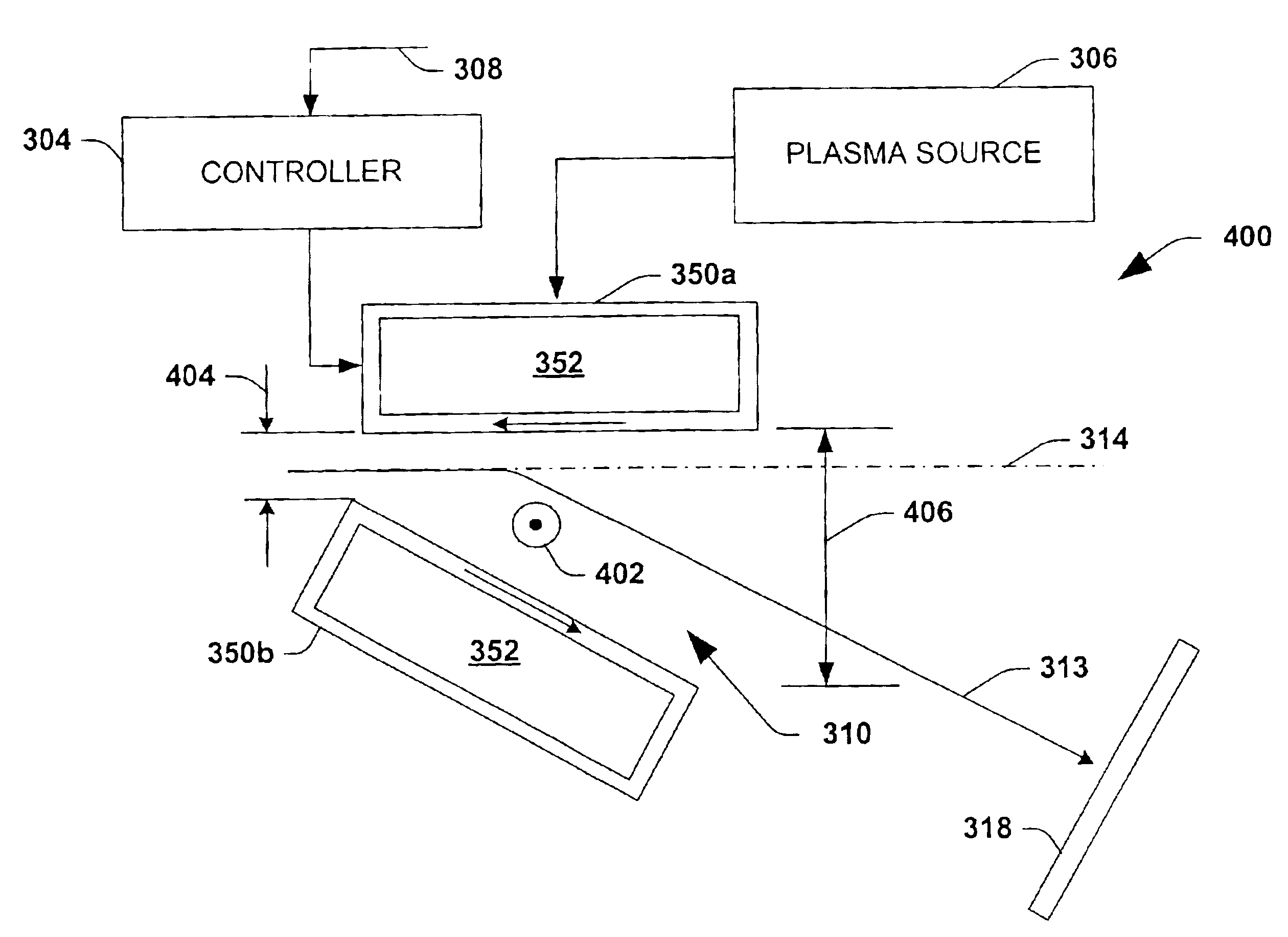
[0009]In accordance with one aspect of the present invention, the magnetic deflector comprises a pair of coils positioned above and below the ion beam, respectively. The coils, upon conduction of current therethrough, operate to generate a magnetic field between the coils that is oriented substantially perpendicular to the direction of beam travel. The coils preferably extend laterally along the entire width of the beam when the beam is ribbon-shaped or scan to appear as a ribbon beam, thereby providing a uniform magnetic field along the entire beam width. In addition, plasma may be introduced into the region between the coils to facilitate in a neutralization of space charge, particularly at low beam energies. The plasma may diffuse along the magnetic field lines between the coils to provide for substantial uniform space charge neutralization along the width of the beam.
[0010]In accordance with another aspect of the present invention, a hybrid magnetic and electrostatic deflector system is employed within an implantation system. The hybrid deflector system comprises a magnetic deflector module and an electrostatic deflector module, along with a controller that is operable to selectively activate one of the modules based upon one or more input control signals. For example, the controller is operable to activate the magnetic deflector module when the input control signal(s) indicates that a mass-energy product is less than a predetermined threshold and activate the electrostatic deflector module when the mass-energy product is greater than the threshold. In the above manner, the hybrid system employs magnetic deflection at low beam energies, wherein plasma may be employed to mitigate the impact of space charge effects that may be problematic at low energies. Likewise, the hybrid system may employ electrostatic deflection at higher beam energies when space charge effects are less pronounced and where magnetic rigidity limits may be experienced.

Problems solved by technology

At low energies, the beam current capability often drops substantially due to poor beam transport efficiency through the various optical elements within the beamline.
Deceleration systems such as the one described above, however, sometimes produce undesirable energy contamination at the workpiece.

Method used


Image

  • Hybrid magnetic/electrostatic deflector for ion implantation systems
  • Hybrid magnetic/electrostatic deflector for ion implantation systems
  • Hybrid magnetic/electrostatic deflector for ion implantation systems

Examples


Embodiment Construction

[0025]The present invention will now be described with reference to the drawings wherein like reference numerals are used to refer to like elements throughout. The illustrations and following descriptions are exemplary in nature, and not limiting. Thus, it will be appreciated that variants of the illustrated systems and methods and other such implementations apart from those illustrated herein are deemed as falling within the scope of the present invention and the appended claims.

[0026]The present invention pertains to a deflection system employed in conjunction with a deceleration system to obtain a low energy ion beam. The deflection system is configured to receive an ion beam and deflect the beam from an incoming beamline axis toward the workpiece in order to prevent neutral particles from reaching the workpiece. As will be further appreciated below, the present invention includes a magnetic deflector that is operable to deflect the beam away from the beamline axis. The magnetic ...


PUM


Abstract

A magnetic deflector for an ion beam is disclosed and comprises first and second coils. The coils are positioned above and below the beam, respectively, and extend along a width of the beam. Current passes through the coils to generate a magnetic field therebetween that is generally perpendicular to a direction of travel of the beam along substantially the entire width thereof. In another aspect of the invention, a method of deflecting a beam prior to implantation into a workpiece is disclosed. The method includes determining one or more properties associated with the beam and selectively activating one of a magnetic deflection module and an electrostatic deflection module based on the determination.

Description

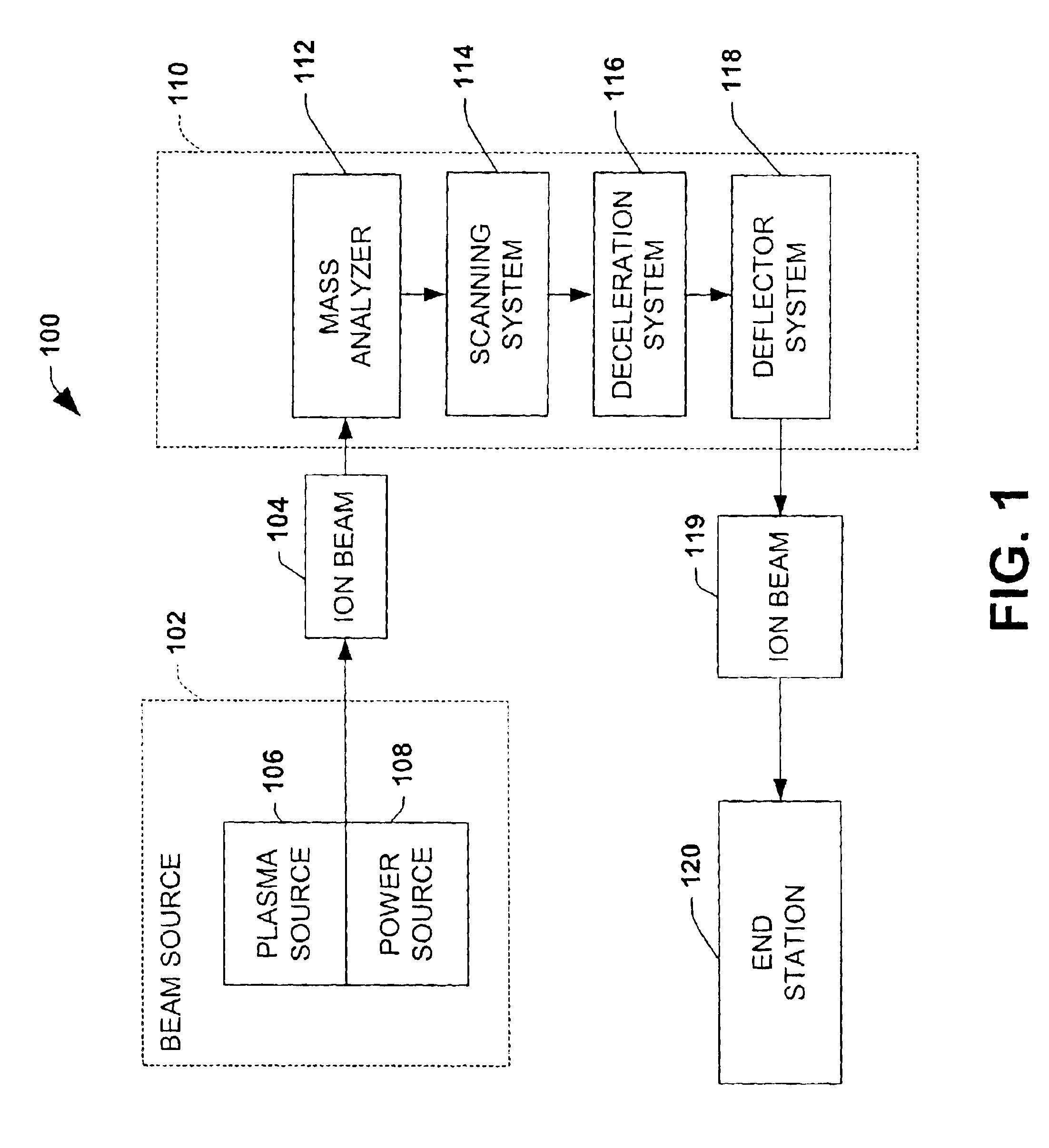
[0001]This application claims priority to U.S. Application No. 60 / 470,926 filed May 15, 2003, which is entitled “High Mass Resolution Magnet for Ribbon Beam Ion Implanters”.FIELD OF THE INVENTION[0002]The present invention relates generally to ion implantation systems, and more particularly to a deflector system employed in an ion implantation system to decelerate an ion beam to low energies.BACKGROUND OF THE INVENTION[0003]Ion implantation systems are used to dope semiconductors with impurities in integrated circuit manufacturing. In such systems, an ion source ionizes a desired dopant element, which is extracted from the source in the form of an ion beam. The ion beam is typically mass analyzed to select ions of a desired mass / charge ratio and then directed at the surface of a semiconductor wafer in order to implant the wafer with the dopant element. The ions of the beam penetrate the surface of the wafer to form a region of desired conductivity, such as in the fabrication of tran...

Claims


Application Information

Patent Timeline
Patent Type & Authority Patents(United States)
IPC IPC(8): H01J37/30H01J27/18H01J27/16H01J37/147H01J37/317H01J37/00H01J37/05
CPCH01J37/05H01J37/3171H01J37/147H01J2237/057H01J37/30
Inventor BENVENISTE, VICTOR M.RATHMELL, ROBERT D.HUANG, YONGZHANG
Owner AXCELIS TECHNOLOGIES
Learn More