DC to DC converter and power management system

Inactive Publication Date: 2005-04-19
INT POWER SYST
View PDF9 Cites 75 Cited by
  • Summary
  • Abstract
  • Description
  • Claims
  • Application Information

AI Technical Summary

Benefits of technology

[0006]Improved Boost DC to DC Converters are also provided which reduce noise and ripple currents in low voltage/high current applications. According to one embodiment, a resonant capacitance is provided by two resonant capacitors which store voltage usi

Problems solved by technology

Conventional DC to DC converters and their associated inverter designs and products have several deficiencies that make it difficult for them to adequately meet the functional requirements of modem hybrid power systems.
These conventional converters are therefore unable to sat

Method used


Image

  • DC to DC converter and power management system
  • DC to DC converter and power management system
  • DC to DC converter and power management system

Examples


Example

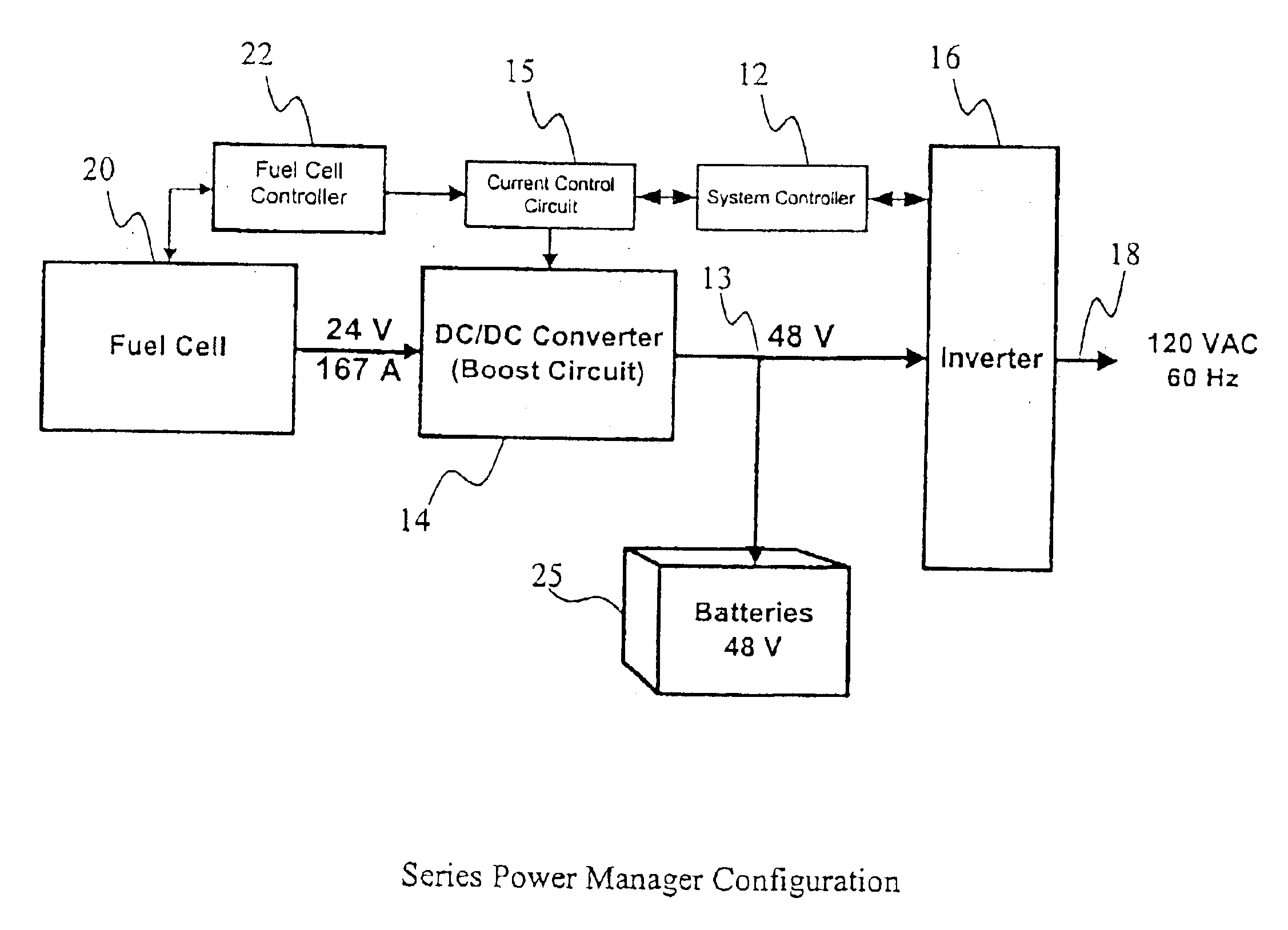
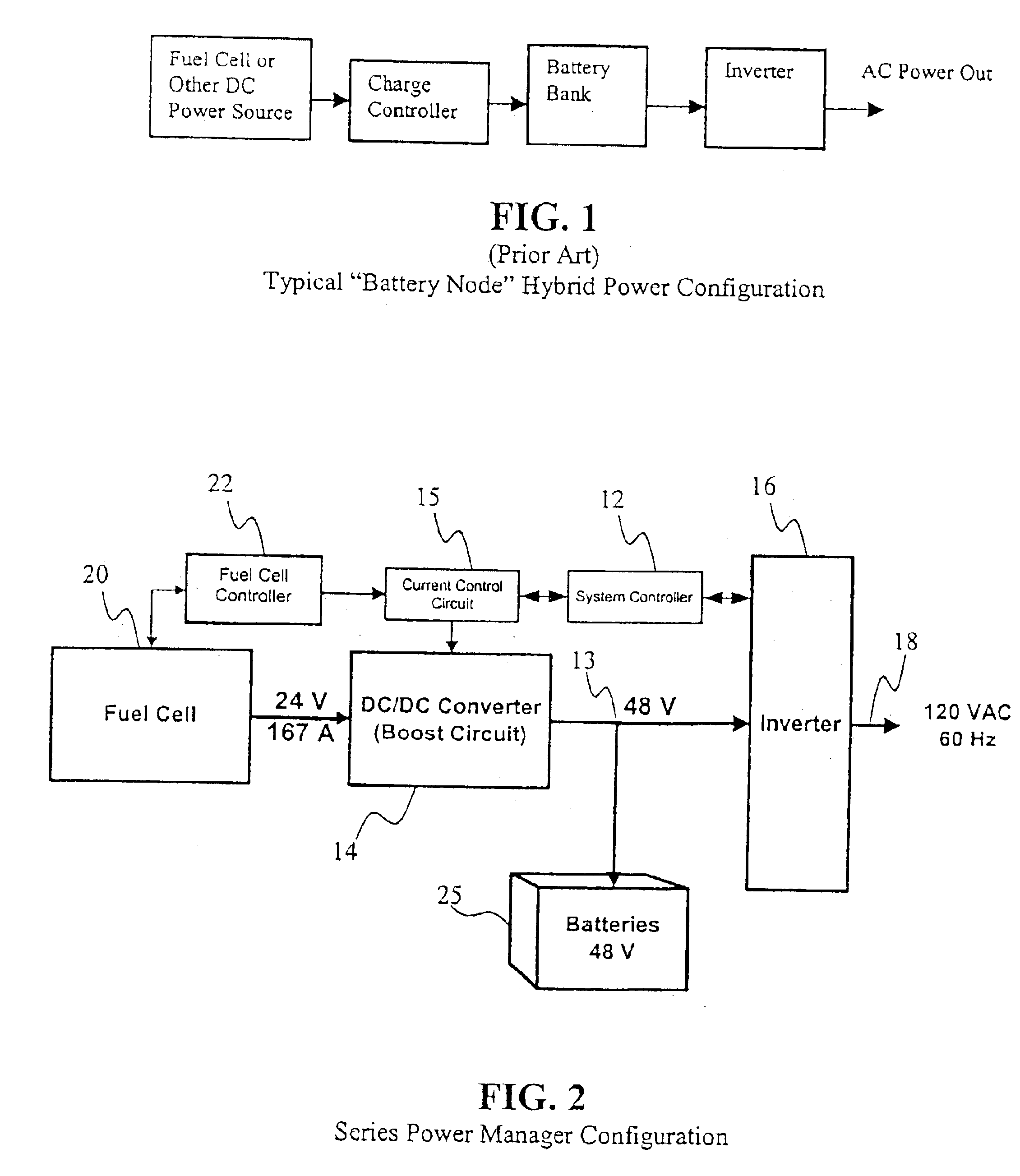
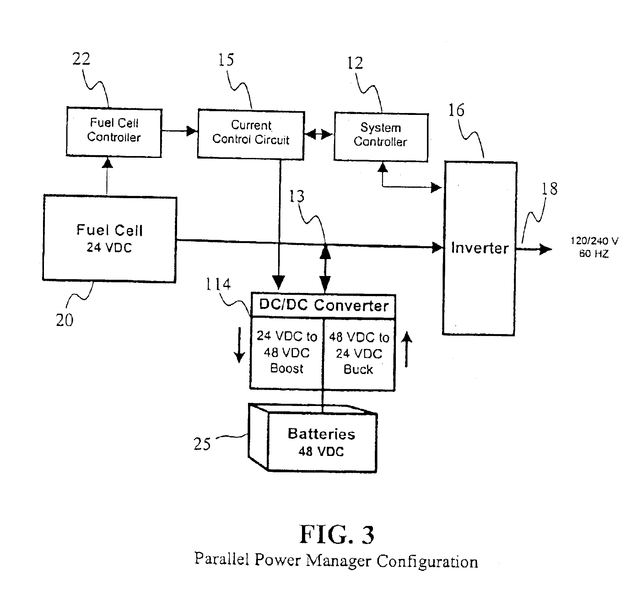
[0017]There are presently two preferred Power Management System configurations according to this invention, including a series converter configuration, illustrated in FIG. 2, and a parallel converter configuration, shown in FIG. 3. In FIGS. 2 and 3, the hybrid power systems 10, 110 of these two embodiments are shown having only a fuel cell 20 and a battery bank 25. It should be noted, however, that the fuel cell 20 could easily be replaced by any other DC power source, by a rectified AC source, or by an energy storage unit, as desired. Similarly, the battery bank 25 could be replaced by a flywheel energy storage unit or other energy storage device that is charged with and discharges direct current. It should also be noted that any number of fuel cells 20 and DC to DC Converters 14 can be arranged in parallel to supply current to the inverter. And furthermore, the single battery bank 25 could be replaced by any number of parallel battery banks or strings connecting to the common bus....


PUM


Abstract

A DC to DC Converter includes an electrical circuit that allows batteries and other electrical energy storage devices to be charged from or to discharge to a variable voltage DC bus. This electrical circuit also enables seamless integration with other energy storage devices and/or DC power sources, such as fuel cells, to provide DC power for a Power Management System. A Power Management System preferably provides both full power source management and power conditioning. The Power Management System is able to manage power flow to and from multiple, isolated power sources and energy storage devices to deliver high quality alternating current (“AC”) power to a load.

Description

[0001]This application is a continuation of U.S. patent application Ser. No. 09 / 917,256, filed on Jul. 27, 2001 now U.S. Pat. No. 6,628,011, which claims priority from U.S. Provisional Application No. 60 / 221,596, filed on Jul. 28, 2000 and is incorporated herein in its entirety by reference.BACKGROUND OF THE INVENTION[0002]This invention relates generally to systems and methods for managing direct current (“DC”) power. More specifically, this invention relates to DC to DC converters and power management systems and methods.[0003]Today, most hybrid fuel cell / battery power systems, and other systems having multiple DC power sources and batteries, are arranged as shown in FIG. 1. The arrangement shown in FIG. 1 is referred to as the “battery node” approach because the power must pass through the battery output node at the battery voltage. This configuration therefore uses battery charge controller and inverter ratings that match the capacity of the fuel cell.[0004]Conventional DC to DC...

Claims


Application Information

Patent Timeline
IPC IPC(8): H02M3/158H02M3/155H02M3/04H02J7/34H02M1/34
CPCH02J7/34H02M1/34H02M3/155H02M3/158Y02B40/90H02M2001/342Y02B70/1491Y02B70/10H02M1/342Y02B40/00
Inventor DROPPO, GERALD W.SCHIENBEIN, LAWRENCE A.HARRIS, BRENT EARLEHAMMERSTROM, DONALD J.
Owner INT POWER SYST
Why Eureka
Try Eureka