Auxiliary active clamp circuit, a method of clamping a voltage of a rectifier switch and a power converter employing the circuit or method

a technology of rectifier switch and active clamp circuit, which is applied in the field of power electronics, can solve the problems of more loss, less efficiency of power converter, and parametric elements, and achieve the effects of less loss, less efficiency, and less loss

a technology of rectifier switch and active clamp circuit, which is applied in the field of power electronics, can solve the problems of more loss, less efficiency of power converter, and parametric elements, and achieve the effects of less loss, less efficiency, and less loss

US6882548B1Inactive Publication Date: 2005-04-19ABB (SCHWEIZ) AG

Image

  • Auxiliary active clamp circuit, a method of clamping a voltage of a rectifier switch and a power converter employing the circuit or method
  • Auxiliary active clamp circuit, a method of clamping a voltage of a rectifier switch and a power converter employing the circuit or method
  • Auxiliary active clamp circuit, a method of clamping a voltage of a rectifier switch and a power converter employing the circuit or method

Examples


Embodiment Construction

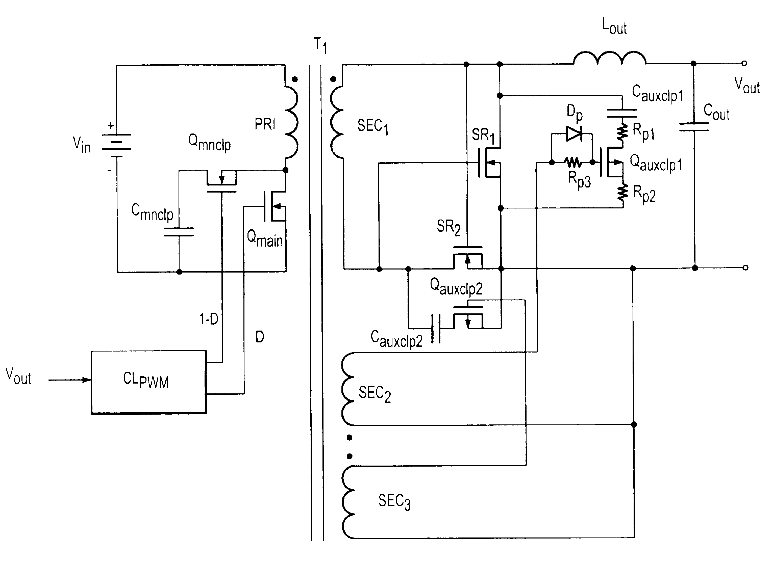
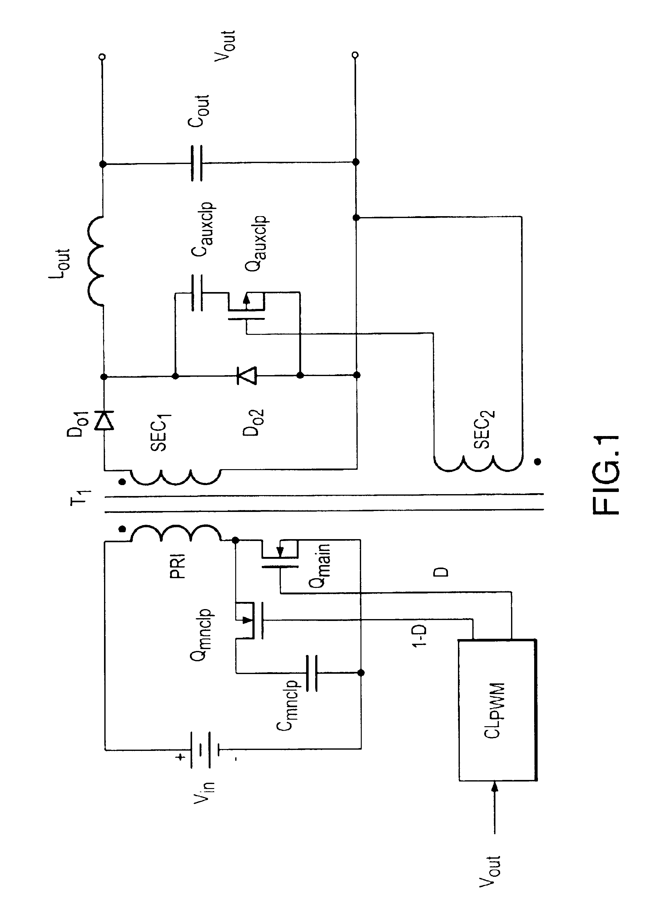
[0024]Referring initially to FIG. 1, illustrated is a schematic diagram of an embodiment of a power converter constructed according to the principles of the present invention. The power converter includes a primary power circuit or inverter driven by a controller (e.g., a pulse width modulator controller) CLPWM, a secondary power circuit and a transformer T1 having a primary winding PRI and first and second secondary windings SEC1, SEC2.

[0025]The primary power circuit is coupled to a source of input voltage Vin and the primary winding PRI of the transformer T1 and includes a main power switch Qmain and a main clamp switch Qmnclp that is series-coupled to a main clamp capacitor Cmnclp having a clamping voltage thereacross. In the illustrated embodiment, the main clamp switch Qmain and the main clamp capacitor Cmnclp form a main active clamp circuit, which also functions as a main active clamp transformer reset circuit. It should be understood by those skilled in the art that the main...


PUM


Abstract

The present invention is directed to an auxiliary active clamp circuit and a method of clamping a voltage of a rectifier switch associated with a power converter. The power converter includes a main active clamp circuit associated with a main power switch coupled to a primary winding of a transformer and a rectifier switch coupled to a secondary winding of the transformer. The main power switch conducts during a main conduction period of the power converter and the rectifier switch conducts during an auxiliary conduction period of the power converter. In one embodiment, the auxiliary active clamp circuit includes an auxiliary clamp capacitor, coupled across the rectifier switch, that stores a clamping voltage substantially equal to an off-state voltage of the rectifier switch. The auxiliary active clamp circuit also includes an auxiliary clamp switch, coupled in series with the auxiliary clamp capacitor, that receives a drive signal from a secondary winding and conducts during the main conduction period thereby clamping a voltage across the rectifier switch at about the clamping voltage.

Description

TECHNICAL FIELD OF THE INVENTION[0001]The present invention is directed, in general, to power electronics and, more specifically, to an auxiliary active clamp circuit, method of clamping a voltage of a rectifier switch associated with a power converter and a power converter employing the circuit and method.BACKGROUND OF THE INVENTION[0002]A power converter is a power processing circuit that converts an input voltage waveform into: a specified output voltage waveform. In many applications requiring a DC output, switched-mode DC / DC power converters are frequently employed to advantage. The switched-mode DC / DC power converters generally include an inverter, an input / output isolation transformer and a rectifier on a secondary side of the isolation transformer. The inverter generally includes a main power switch, such as a field effect transistor (“FET”), that converts the DC input voltage to an AC voltage. The input / output isolation transformer, then, transforms the AC voltage to anothe...

Claims


Application Information

Patent Timeline
19 Apr 2005
Publication
US6882548B1
IPC
H02M3/335; H02M3/24; H03K17/0814; H03K17/08; H02M1/34
CPC
H02M1/34; H02M3/33592; Y02B70/1491; H03K17/08142; Y02B70/1475; H02M2001/342; Y02B70/10; H02M1/342
Inventors
JACOBS, MARK E.; PAL, SUBARNA