Eureka AIR delivers breakthrough ideas for toughest innovation challenges, trusted by R&D personnel around the world.

Application method for abradable material

a technology of abradable materials and abradable materials, applied in the direction of application, superimposed coating process, ceramicware, etc., can solve the problems of insufficient mechanical capability of aluminum, adverse effects on fatigue strength and dimensional control, and damage to other components or parts of the component, etc., to achieve excellent thermal protection, light weight, and weight reduction

Inactive Publication Date: 2005-04-26
GENERAL ELECTRIC CO
View PDF21 Cites 25 Cited by
  • Summary
  • Abstract
  • Description
  • Claims
  • Application Information

AI Technical Summary

Benefits of technology

"The present invention provides a method for applying a porous alumina rub material to aircraft engine components, such as turbine shrouds, that require materials with both high abrasion resistance and thermal resistance. The method involves reacting a molten aluminum-based alloy with the surface of the component, allowing for improved abradability and thermal barrier properties. The method may also involve masking certain areas of the component to prevent aluminiding, which can damage fatigue strength and dimensional control. The use of the modified aluminum / alumina wear material is limited due to its abrasive nature, so the method also includes steps to remove the aluminum phase and create a porous alumina coating for improved protection. Overall, the invention provides a more effective solution for protecting against high-temperature damage in aircraft engine components."

Problems solved by technology

Applying the material directly to the aircraft engine component is required because the alumina without the aluminum has insufficient mechanical capability to be used for any purpose other than as a wear material coating.
While some aircraft engine components will benefit from the aluminiding that occurs when the surface of the components are contacted with molten aluminum-based metal, other components, or areas of the component, will be damaged by such aluminiding.
However, by aluminiding other components, and portions of components, fatigue strength and dimensional control will be adversely affected.
For the components, and portions of components, that will be damaged by aluminiding, masking the areas for which aluminiding is undesirable is necessary.
Under certain circumstance, the aircraft engine component may be heated for more than 24 hours, but such a situation would be unusual.
Only aircraft engine components that are alumina formers can be masked in such a manner, as alumina will form a good barrier to molten aluminum, while chromia will not form a good barrier.

Method used


Image

  • Application method for abradable material
  • Application method for abradable material

Examples


Embodiment Construction

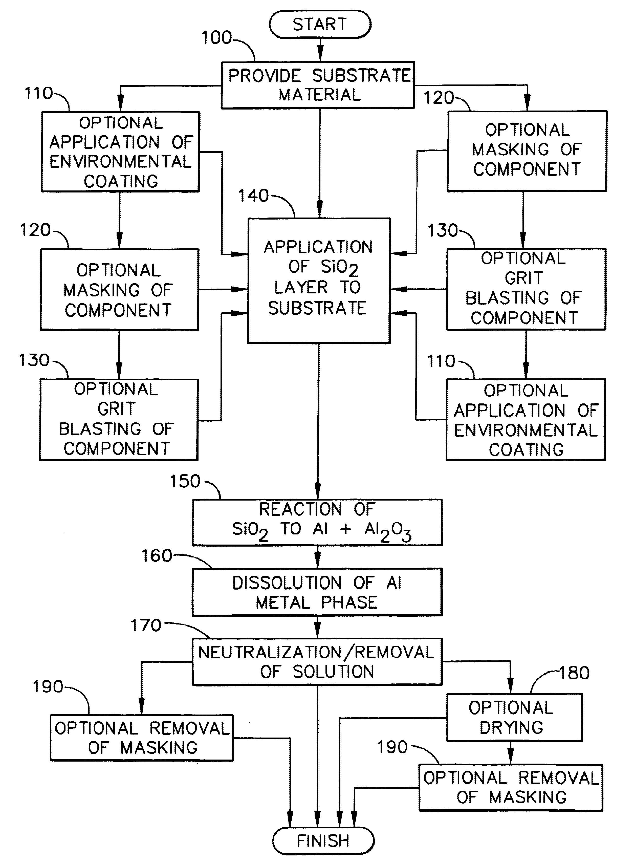
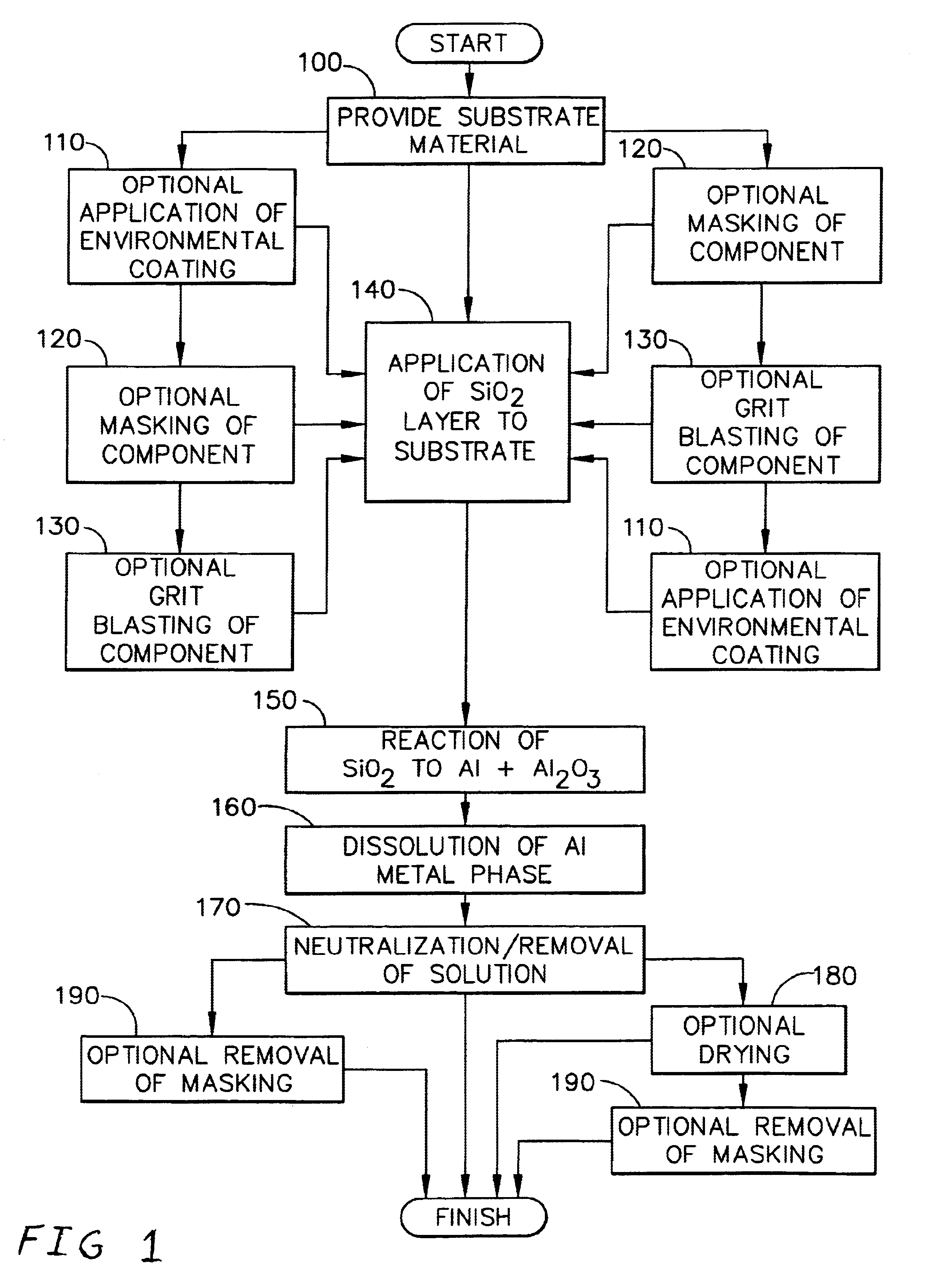
[0030]Referring now to FIG. 1 there is shown the method of the present invention for applying a porous alumina coating to an aircraft engine component at least a portion of which comprises a metallic substrate material. The initial step of the process 100 is the provision of an aircraft engine component. The optional next step of the process is the application of an environmental coating to the aircraft engine component, or any preselected portions of the component, such as MCrAlY or diffusion aluminide, among others 110. The optional next step of the process is masking any preselected portions of the aircraft engine component that would be adversely affected by aluminiding when the molten aluminum alloy is applied in accordance with the methods of the present invention by heating the aircraft engine component in an oxygen containing atmosphere to a preselected temperature in the range of about 1500° F. to about 2350° F. for a preselected period of time. Such a preselected time will...


PUM

PropertyMeasurementUnit
temperatureaaaaaaaaaa
melting pointaaaaaaaaaa
temperaturesaaaaaaaaaa

Abstract

A method for applying a highly porous alumina material that is useful in the hot section of a jet aircraft engine. In order to apply the porous alumina, an aluminum-based metal / alumina material known in the art is first placed onto an aircraft engine component substrate. The aluminum-based metal is then dissolved using a solution that will not affect the alumina or the underlying substrate. The alumina is then washed with deionized water and dried. The aircraft engine component may be first masked by applying a non-porous metal oxide material to the component or by oxidizing the surface of the component. The resulting alumina has a porosity in the range of about 20% to about 45%. The alumina has globular interconnected surface features in the range of about 0.5 μm to about 20 μm.

Description

CROSS-REFERENCE TO RELATED APPLICATIONS[0001]This Application is related to application Ser. No. 10 / 263,870, filed contemporaneously with this Application on Oct. 3, 2002, invented by Mark. D. Gorman, entitled “ABRADABLE MATERIAL FOR CLEARANCE CONTROL”, assigned to General Electric Company the assignee of the present invention, and which is incorporated by reference herein.FIELD OF THE INVENTION[0002]The present invention is directed to a method of applying an abradable alumina material for clearance control for aircraft engine components.BACKGROUND OF THE INVENTION[0003]Modern aircraft are often powered by a propulsion system that includes a gas turbine engine housed within an aerodynamic streamlined nacelle. The major portions of an engine include a fan, compressor, combustor and turbine section. In the turbine portion of the engine, there are static parts and rotating parts. The static boundary at the tip of the rotating parts or blades are referred to as shrouds.[0004]One of the...

Claims


Application Information

Patent Timeline
Patent Type & Authority Patents(United States)
IPC IPC(8): C23C10/00C23C10/22C23C4/12C23C30/00C23C4/14C23C26/02C23C28/00F01D11/08F01D11/12C04B38/04
CPCC04B38/04C23C4/14C23C10/22C23C26/02C23C28/00C23C30/00F01D11/122C04B35/10C04B38/0074C04B2111/00482Y02T50/672Y02T50/67Y02T50/60
Inventor GORMAN, MARK D.
Owner GENERAL ELECTRIC CO
Why Eureka
Eureka Blog
Learn More