
Sensor with amorphous electrode

a technology of amorphous electrodes and sensors, applied in liquid/fluent solid measurement, instruments, machines/engines, etc., can solve the problems of abrasion or wear, design is susceptible to the buildup of contact resistance, and the “open circuit” conditions

Inactive Publication Date: 2005-05-03
DELPHI TECH INC
View PDF21 Cites 37 Cited by
  • Summary
  • Abstract
  • Description
  • Claims
  • Application Information

AI Technical Summary

Benefits of technology

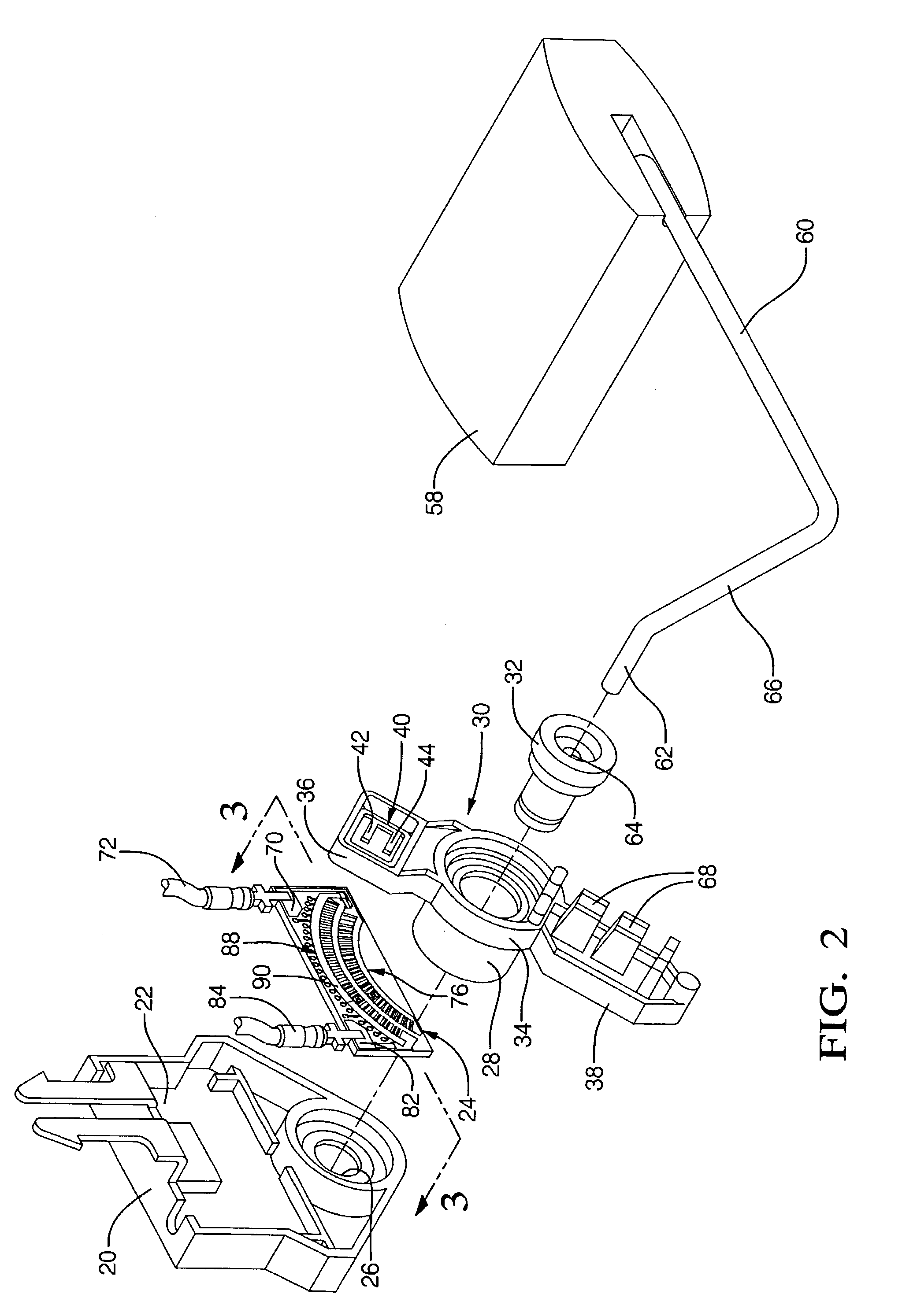
[0007]In one embodiment, a method for detecting fuel level comprises: contacting the fuel level sensor with a fuel in a fuel storage vessel, determining the resistance between the connector lines, and using the resistance to determine the level of the fuel.

Problems solved by technology

Both of these standard designs are susceptible to the buildup of contact resistance.
Contact resistance can change the output value of the resistor assembly or in some instances can cause “open circuit” conditions.
With the designs described above, relatively high forces are used to cause abrasion or wear against the ink / ceramic surface or the metal contact plate.
Contact wear is further aggravated by the presence of the fuel.
Current electrodes employ high amounts of economically costly precious metals in their manufacture.
These precious metals are also vulnerable to the environmental poisons to which they are subjected, thereby diminishing the potential life span of the electrode.

Method used


Image

  • Sensor with amorphous electrode
  • Sensor with amorphous electrode
  • Sensor with amorphous electrode

Examples


example 1

[0053]A thick film ink of 17.0 wt % 1-methoxy-2-propanol acetate solvent, 8.0 wt % butyl acetate solvent, 7.6 wt % acrylic resin binder, 3.2 wt % methyl methacrylate polymer, 9.0 wt % ethanol wetting agent, 51.2 wt % amorphous alloy Pd47Ni47P6, and 6.4 wt % metallic silver, is made, based upon the total weight of the ink. An aluminum oxide fuel ceramic substrate is screen printed with the ink. The ink is fired up to 460° C. for 2 hours. The fired electrode includes 88.9 wt % amorphous alloy and 11.1 wt % metallic silver, based upon the total weight of the fired electrode.

example 2

[0054]Surfaces not intending to be covered on an aluminum oxide substrate are masked off. Amorphous alloy Pd40Ni40Cu15P5

particles in a suspension with nickel sulfamate solution are electroless deposited onto the masked aluminum oxide substrate. A nickel matrix with amorphous alloy inclusions is deposited. The inclusions having a diameter of about 0.5 μm to 10 μm make up about 38 wt % of the electrode volume. The substrate is fired 490° C. for 2 hours. The fired electrode includes 67.9 wt % amorphous alloy and 22.1 wt % nickel, based upon the total weight of the fired electrode.

example 3

[0055]A thick film ink of 34.8 wt % 1-ethoxypropan-2-ol solvent, 5.0 wt % cellulose ethylether resin, 7.0 wt % ethanol wetting agent, 47.6 wt % amorphous alloy Zr55Cu30Ni5Al10, and 5.6 wt % Sn85In11Ag3Cu1 is made, based upon the total weight of the ink. An aluminum oxide fuel ceramic substrate is screen printed with the ink. The ink is fired up to 360° C. for 2 hours. This ink has desirable reflow properties at temperatures as low as 240° C. The fired electrode includes 89.4 wt % amorphous alloy and 10.6 wt % Sn85In11Ag3Cu1, based upon the total weight of the fired electrode.


PUM

PropertyMeasurementUnit
total thicknessaaaaaaaaaa
thicknessaaaaaaaaaa

Abstract

Disclosed herein are sensors, and method for making an using the same. In one embodiment, the sensor comprises: a first electrode disposed on a ceramic substrate, wherein the first electrode comprises an amorphous metal material comprising a first metal selected from the group consisting of a Group 9 metal, a Group 10 metal, a Group 11 metal, and combinations comprising at least one of the foregoing first metals, and zirconium or at least one of phosphorus and boron.

Description

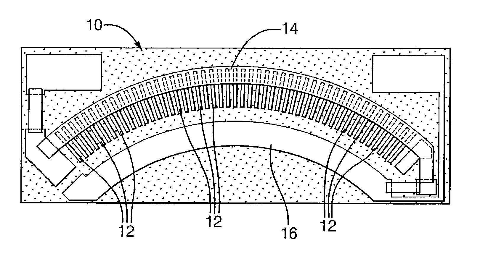
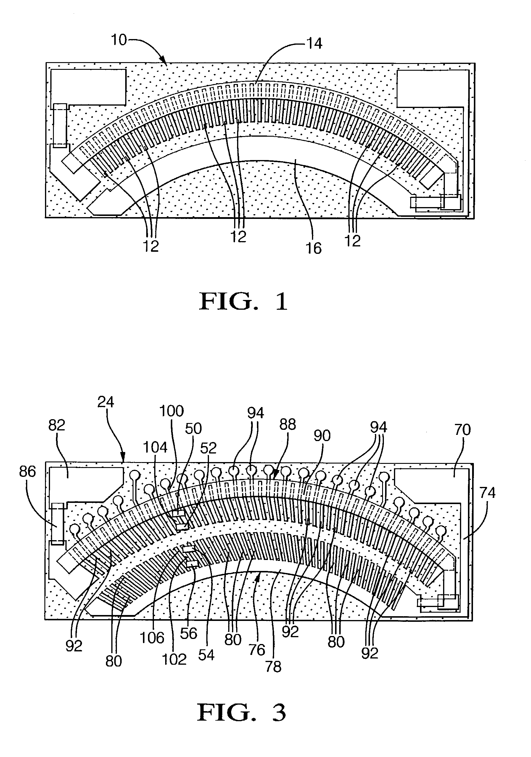
BACKGROUND OF THE INVENTION[0001]In a first standard design, contacts located on a wiper assembly form a shorting bar across a resistor on the ceramic card and a conductor on the ceramic card. A prior art ceramic resistor card 10 is shown in FIG. 1. A wiper button makes contact at designated intervals with conductive bars 12 emanating from a resistive ink 14 printed over the conductive bars. A second wiper button rides on a flat continuous conductive path 16 screened onto the ceramic substrate. An alloy of copper, zinc and nickel known as “silver nickel” is used as a material for the contacts due to the relative softness of this material and its relative low cost. Substantial material volume must be utilized to allow for the significant contact wear to insure part durability.[0002]In a second standard design, contacts located on the wiper assembly form a shorting bar across a resistor on a ceramic card and a metal conductor plate. The wiper contact button makes contact at designated...

Claims


Application Information

Patent Timeline
Patent Type & Authority Patents(United States)
IPC IPC(8): G01F23/30G01F23/36
CPCG01F23/363
Inventor LABARGE, WILLIAM J.ANDERSON, CONRAD H.IRELAND, HUGH W.
Owner DELPHI TECH INC
Features
  • Generate Ideas
  • Intellectual Property
  • Life Sciences
  • Materials
  • Tech Scout
  • Unparalleled Data Quality
  • Higher Quality Content
  • 60% Fewer Hallucinations
Learn More