Optical fiber fixing method

a technology of optical fiber and fixing method, which is applied in the direction of instruments, other domestic objects, optical elements, etc., can solve the problems of short splicing time, large optical fiber connection loss, and long time-consuming fixing method using adhesive, so as to achieve less influence on the environment

Inactive Publication Date: 2005-05-03
YAZAKI CORP
View PDF7 Cites 26 Cited by
  • Summary
  • Abstract
  • Description
  • Claims
  • Application Information

AI Technical Summary

Benefits of technology

[0030]In accordance with the above configuration, because the laser beam is excited in the pulse exciting system, the laser welding can be performed with a shallow welding depth and less influence on the environment.

Problems solved by technology

The latter connector connection has a disadvantage of great connection loss of the optical fiber resulting from axis displacement, axis inclination, etc., but has an advantage of a short splicing time.
However, the fixing method using the adhesive takes a long time to heat and harden the adhesive.
This presents problems of low productivity of the optical connector, of changes in the bonding strength due to the surface property (surface wettability, surface coarseness, etc.) and of low heat resistance.
However, the conventional fixing method presents the following problem to be solved.
Firstly, because the ferrule 63 is irradiated with the laser beam 61 from its end surface, the molten area is so small that fixing cannot be assured.
Specifically, in some places, the laser beam 63 is strongly applied and the fiber wire may be damaged, whereas in other places, the laser beam 63 is weakly applied and the fiber wire may be insufficiently heated.
In this case, the fiber wire consisting of a core and cladding may generate thermal cracks.
However, in this case, the heating becomes insufficient so fixing cannot be assured.

Method used


Image

  • Optical fiber fixing method
  • Optical fiber fixing method
  • Optical fiber fixing method

Examples


Embodiment Construction

[0039]Now referring to the drawings, a detailed explanation will be given of an embodiment of the present invention.

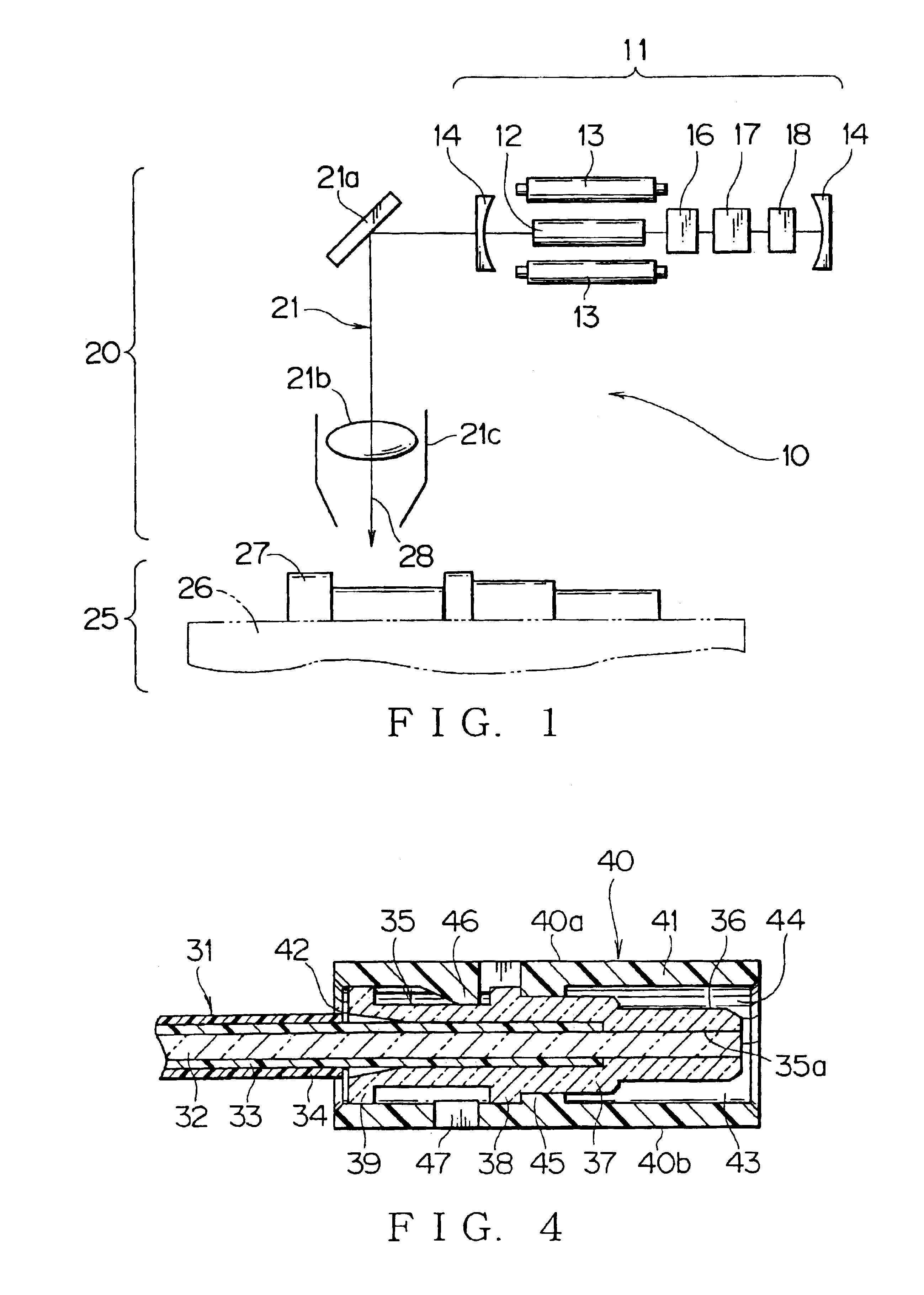
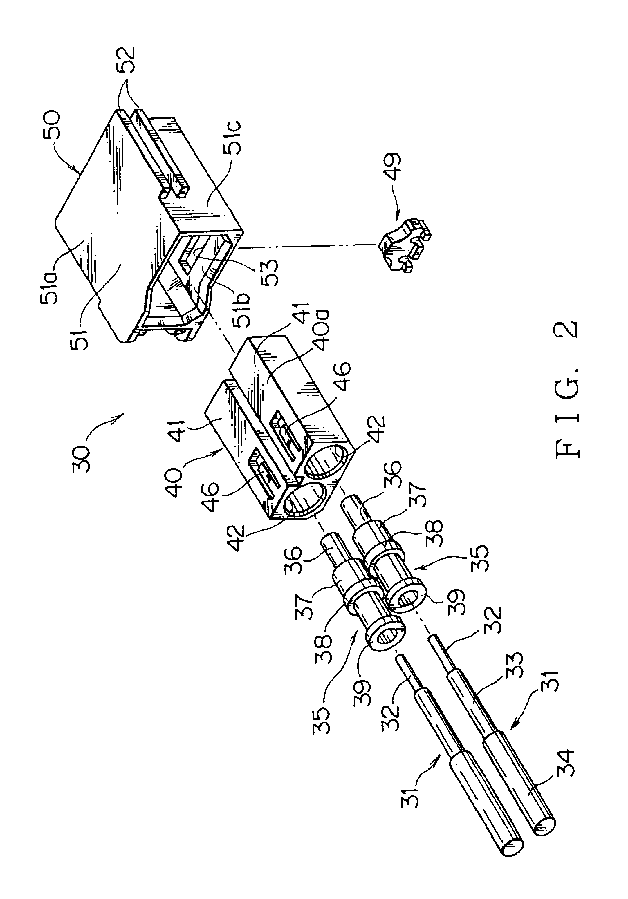
[0040]FIGS. 1 to 4 show an embodiment of an optical fiber fixing method according to the present invention.

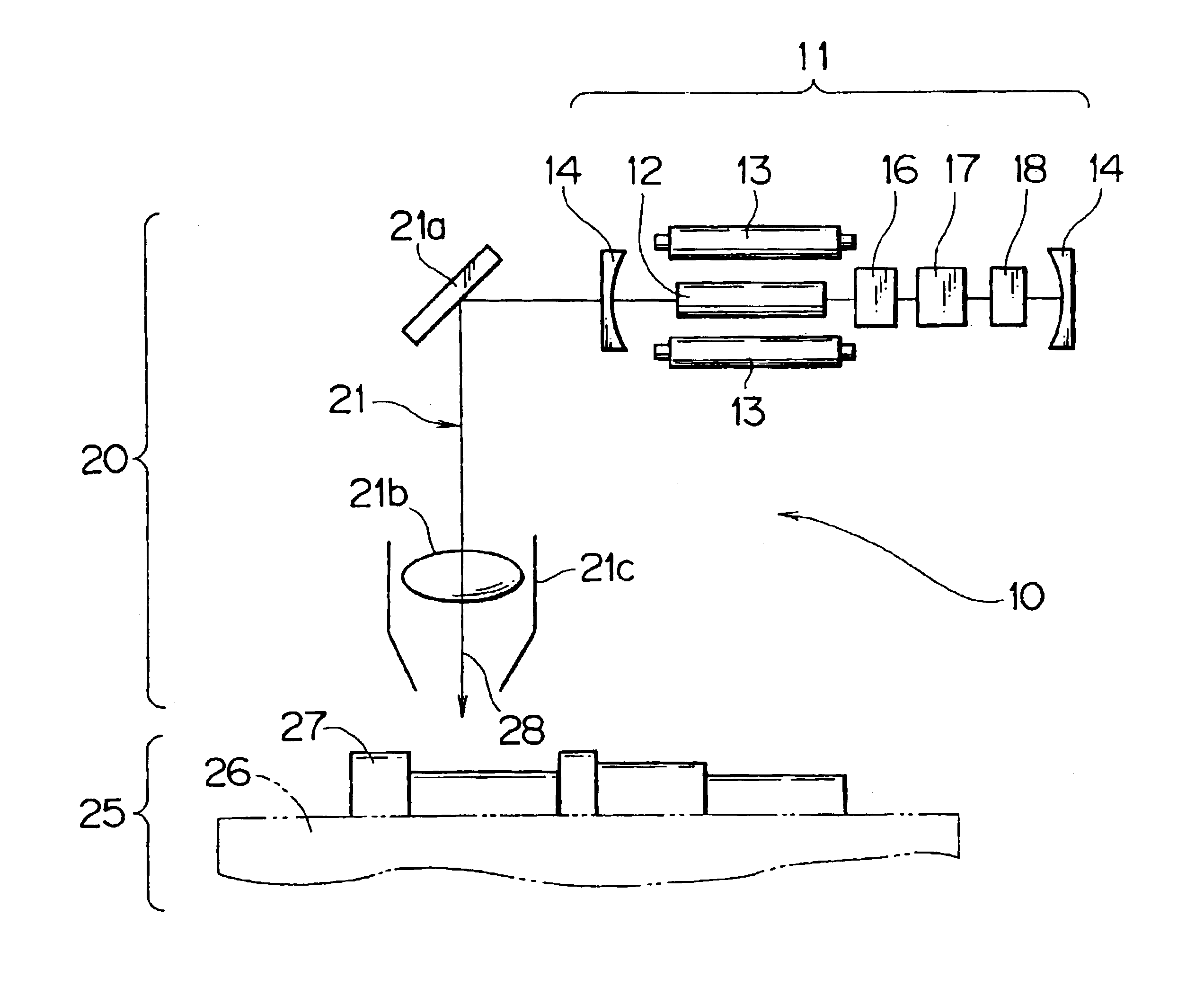
[0041]FIG. 1 shows a basic configuration of a YAG laser processing machine 10 which is employed in this embodiment. The YAG laser processing machine 10 includes a laser oscillator 11, a processing optical system 20 and a workpiece system 25 to be processed.

[0042]The basic configuration of the laser oscillator 11 includes at least one host member (rod) 12, an exciting lamp 13 and a pair of beam condensing reflecting mirrors 14. The host member 12 is cylindrical and made of a YAG (yttrium aluminum garnet) crystal doped with Nd (neodymium). The laser output is integer-times as large as the host member 12.

[0043]The exciting lamp 13 is a pumping device for injecting energy into the host member 12 and induced-emitting light. A pair of exciting lamps are arranged on both...


PUM

PropertyMeasurementUnit
frequencyaaaaaaaaaa
frequencyaaaaaaaaaa
frequencyaaaaaaaaaa

Abstract

While a ferrule or a laser beam is being shifted in an axial direction, the laser beam is applied, thereby forming a plurality of welded portions at the boundary between a coating of an optical fiber and the ferrule. A YAG laser in a Q switch pulse mode is used to provide a laser beam. The beam. The YAG laser in the Q switch pulse mode is preferably oscillated in a pulse exciting system. The ferrule is made of transparent or semi-transparent synthetic resin. The coating of the optical fiber is made of translucent synthetic resin. In this way, an optical fiber fixing method can be provided which can surely fix an optical fiber and a ferrule in a shortened time, and minimize the thermal influence on the vicinity of the portion to be processed.

Description

BACKGROUND OF THE INVENTION[0001]1. Field of the Invention[0002]The present invention relates to an optical fiber fixing method for fixing a ferrule, which is a terminal component for optical communication, and an optical fiber to each other.[0003]2. Description of the Related Art[0004]As well known, a method of connecting optical fibers to each other is roughly classified into a permanent connection in which they cannot be disconnected after once connected, and a connector splicing in which they can be freely disconnected even after being once connected. The permanent connection is utilizes a technique of fusion splicing or bonding splicing. The connector splicing fits connectors (one is a plug, and the other is a receptacle) to each other so that the end surfaces of optical fibers are physically spliced to each other.[0005]The latter connector connection has a disadvantage of great connection loss of the optical fiber resulting from axis displacement, axis inclination, etc., but h...

Claims


Application Information

Patent Timeline
Patent Type & Authority Patents(United States)
IPC IPC(8): G02B6/38G02B6/36
CPCB29C65/1635B29C66/5344G02B6/3855G02B6/3879B29C66/232B29C65/1654B29C66/65B29C66/652B29K2023/06B29K2027/06B29K2027/12B29K2033/12B29K2069/00B29K2077/00B29L2011/00B29L2031/731B29C65/00B29C66/1122B29C66/71B29C66/7392
Inventor ENDO, TAKASHI
Owner YAZAKI CORP
Why Eureka
Try Eureka