Focused ion beam apparatus

a technology of focusing ion beam and focusing beam, which is applied in the field of focused ion beam apparatuses, can solve the problems of difficult to correct drifts by pattern matching technique, difficulty in conducting a specified fine processing, and limitation of hardware improvement, so as to facilitate recognition of patterns and easy to obtain the position of linear lines. , the effect of easy recognition

Inactive Publication Date: 2005-05-03
HITACHI HIGH TECH SCI CORP
View PDF6 Cites 16 Cited by
  • Summary
  • Abstract
  • Description
  • Claims
  • Application Information

AI Technical Summary

Benefits of technology

[0013]When a sample irradiation current is increased, the thickness (i.e., the width) of the straight line segment of the linear line pattern becomes to be greater, and its image also becomes thicker (i.e., wider). However, one side and the other side of the straight line segment of the linear line pattern about a center line of the pattern in the image are broadened by the same amount in both ways in directions perpendicular to the extension direction of the straight line. Accordingly, by using the average position of the measured positions of the straight line taken from the mutually opposite directions perpendicular to the straight line segment, the position of the focused ion beam in the direction perpendicular to the linear line pattern, which does not depend on the sample irradiation current at the time of forming the linear line pattern, can be more accurately determined. As a result, even when the sample irradiation current changes, in other words, even when the thickness of the linear line pattern changes, the irradiation position of the focused ion beam can be accurately corrected.
[0015]In general, one of the main objects of the fine processing is to form a cross section in a sample for observation of the cross section, or to create a TEM sample. In this case, to achieve the object, drifts in a direction perpendicular to the cross section to be formed need to be accurately corrected. However, some drifts may be permitted in a direction in parallel with the cross section to be formed. A focused ion beam apparatus may intrinsically have drifts, but in accordance with one embodiment of the present invention, a method for correcting a beam irradiation position in fine processing with such a focused ion beam apparatus may allow some drifts of the focused ion beam apparatus in a direction in parallel with a cross section to be created, and correct drifts only in at least one direction with respect to the cross section to be created, preferably in a direction perpendicular to the cross section to be created, which requires more strict drift control. Accordingly, the method for correcting a beam irradiation position in fine processing in accordance with the present embodiment gives attention to the fact that the required accuracy level for drift correction differs depending on directions with respect to a cross section to be created, and may obtain a drift correction amount only in at least one direction with respect to a cross section to be created. The embodiment of the present invention is effective in realizing a highly accurate drift correction only in a specified direction that requires a higher drift correction accuracy.
[0016]In one aspect of the present embodiment, since brightness changing points are linearly continuous due to the fact that a linear line pattern is formed on a sample surface, the recognition of the pattern can be facilitated. For example, an algorithm that searches maximum brightness changing points in a direction perpendicular to the formed linear line may be used to create a linear line recognition algorithm that successively obtains maximum brightness changing points along the linear line pattern and determines as to whether or not a row of the points thus obtained is linearly continuous. With such a simple linear line recognition algorithm, the linear line pattern can be readily recognized even when the sample surface has roughness, and the need for forming a deposition film is obviated.
[0017]Brightness information may be integrated in a direction of the linear line pattern to obtain one brightness profile in a direction perpendicular to the linear line pattern. Even when the sample surface has some roughness, the brightness profile shows few brightness changes in regions outside of is the linear line pattern and maximum brightness changes within the linear line pattern due to the affect of the integration, such that the position of the linear line can be readily obtained based on the brightness profile. As a result, the position of the linear line can be measured without the need to form a deposition film. Because there is no need to form a deposition film, the processing time required to form a reference pattern can be shortened. The short processing time required to form a reference pattern is effective at least in the following aspects.
[0018]The short processing time improves the operability of the focused ion beam apparatus. Prior to a fine processing on a sample, a sample image of the sample is obtained and various settings are made (for example, various processing frames are set) for the fine processing. Then, a reference pattern in a linear line configuration may be automatically formed at a position where a relative positional relation with a position of a section in the sample that is subject to the fine processing is preset. During the fine processing work, the reference pattern is periodically observed, drifts of the beam irradiation position are measured through recognizing the linear line pattern, and the drifts of the beam irradiation position can be corrected with respect to the section in the sample that is subject to the fine processing. The reference pattern can be formed in a substantially shorter time, and therefore the actual fine processing work can be started with a substantially shorter waiting time during which the reference pattern is formed. Therefore, an operator of the focused ion beam apparatus can readily use the drift correction function that limits correction of drifts only in at least one specified direction, without a substantial increase in the waiting time.
[0019]Secondly, the short processing time improves the accuracy in the position of fine processing. A drift of the beam irradiation position that may occur during a period between the start of fine processing and the completion of forming a reference pattern in a linear line configuration cannot be corrected. However, the amount of the drift during such a period can be ignored if the time for forming the reference pattern in a linear line configuration is short.

Problems solved by technology

When a fine processing is conducted through irradiation of an ion beam, the irradiated position (or focused position) of the ion beam may shift due to a variety of factors, which may often make it difficult to conduct a specified fine processing.
However, the improvement in hardware has its limitation.
Accordingly, when a series of fine processings are performed through changing the sample irradiation beam current, it is difficult to correct drifts by the pattern matching technique.
However, the conventional pattern correction method entails the following problems in forming the reference patterns in dots.
One of the problems is that samples may not often have a flat surface on which dot patterns are formed.
In this case, it is difficult to discriminate roughness (i.e., concave sections and convex sections) that are originally present on the sample surface from the dots formed.
However, after repeatedly scanning the reference pattern region, the deposition film is finally etched, and the original surface roughness of the sample may possibly reveal.
However, when there are a few specific points with brightness recognizably different from that of the surrounding, the accuracy in measuring positions cannot be increased to a required level.
However, when the reference pattern region is scanned to obtain a reference pattern image, the entire group of the specific points may not possibly be contained inside the image area obtained by scanning the reference pattern region if the amount of drift is large.
For this reason, even when the creation of dot patterns is automated so that an operator can preset processing conditions, and dot patterns for drift correction are automatically created according to the preset processing conditions, it is difficult to guarantee if the drift correction operation is reliably performed.

Method used


Image

  • Focused ion beam apparatus
  • Focused ion beam apparatus
  • Focused ion beam apparatus

Examples


Embodiment Construction

[0031]Preferred embodiments of the present invention will be described below with reference to the accompanying drawings.

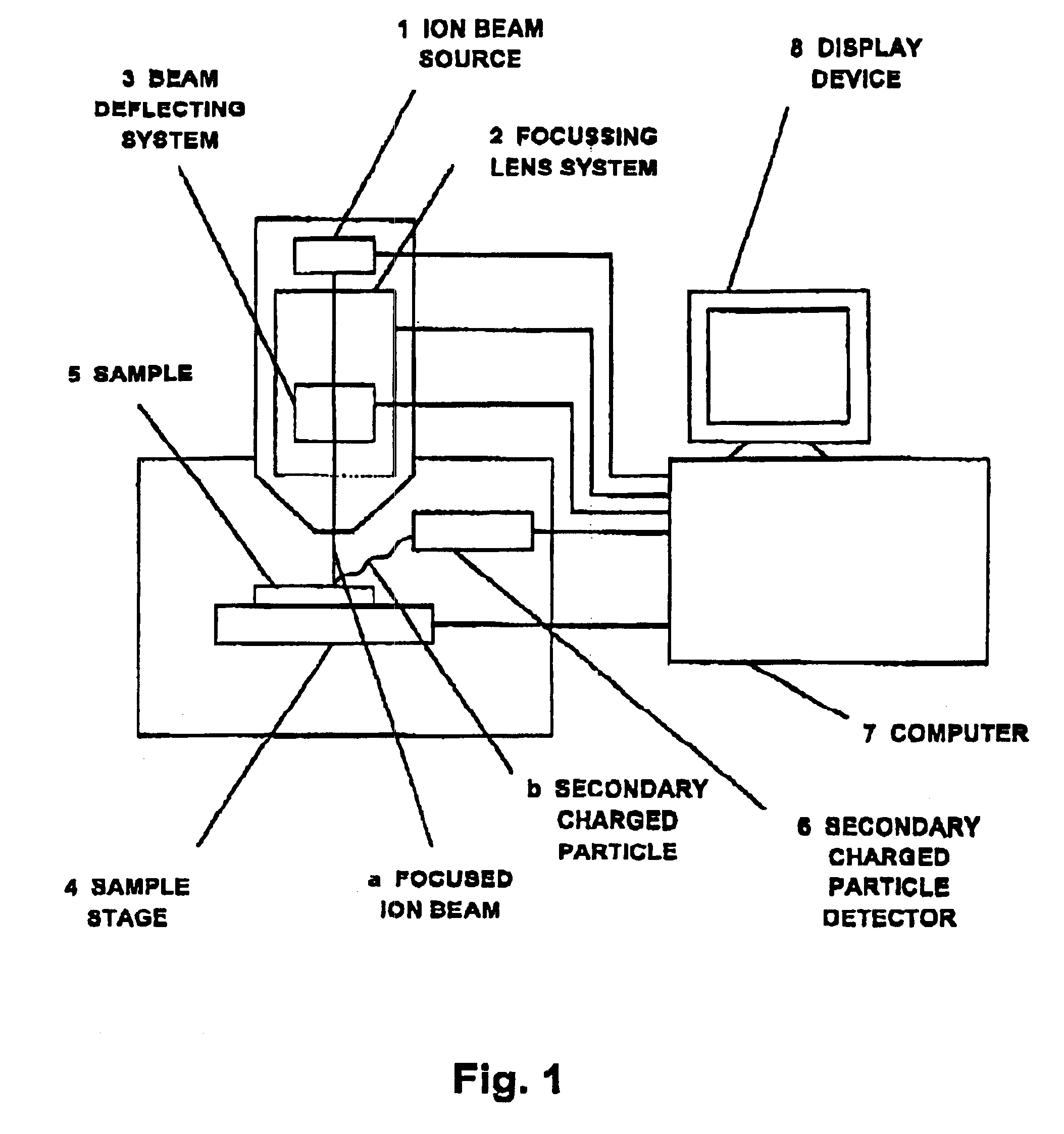
[0032]FIG. 1 schematically shows a structure of a focused ion beam system in accordance with an embodiment of the present invention. The focused ion beam system includes a focused ion beam source 1 that generates an ion beam a. The ion beam a passes through a focusing lens system 2 and a beam deflection system 3, and is irradiated on a sample 5 that is mounted on a sample stage 4. When the ion beam a passes through the focusing lens system 2, the ion beam a is converged by the lens effect of the focusing lens system 2 and irradiated as a focused ion beam on the sample 5. The focusing lens system 2 includes a variable aperture switching function that provides a plurality of different aperture diameters. By changing settings at the focusing lens system 2, the beam current of the focused ion beam a irradiated on the sample 5 can be changed. Secondary charged particle...


PUM


Abstract

A method for correcting drifts in beam irradiation position in a focused ion beam apparatus is disclosed. A linear line pattern is formed on a sample by linearly irradiating a focused ion beam at a location removed from a processing region where a cross section is to be formed in the sample. The linear line pattern extends in a direction in parallel with a surface of the cross section to be formed. By referring to the linear line pattern while a specified section of the sample is processed, the beam irradiation position of the focused ion beam with respect to the linear line pattern is measured in a direction perpendicular to the linear line pattern to detect a drift in the beam irradiation position of the focused ion beam in the direction perpendicular to the linear line pattern. The beam irradiation position of the focused ion beam is corrected based on the drift detected with respect to the processing region.

Description

BACKGROUND OF THE INVENTION[0001]1. Field of the Invention[0002]The present invention generally relates to focused ion beam apparatuses, and more particularly to methods and devices for correcting beam irradiation positions in focused ion beam apparatuses, which overcomes the problems associated with a fine processing that employs ion beam irradiation in which an irradiated position of ion beam may shift during the fine processing.[0003]2. Related Background Art[0004]When a fine processing is conducted through irradiation of an ion beam, the irradiated position (or focused position) of the ion beam may shift due to a variety of factors, which may often make it difficult to conduct a specified fine processing. In particular, due to further miniaturization in the semiconductor device design rule, the positional accuracy that is required in a fine processing has reached a level of 100 nm or below. In order to realize such a positional accuracy, the amount of drift, i.e., a shift of irr...

Claims


Application Information

Patent Timeline
Patent Type & Authority Patents(United States)
IPC IPC(8): H01J37/30H01J37/305H01J37/304H01J37/04H01J37/317
CPCH01J37/3056H01J37/3045
Inventor IKKU, YUTAKA
Owner HITACHI HIGH TECH SCI CORP
Why Eureka
Try Eureka