Composite magnetic body, and magnetic element and method of manufacturing the same

a magnetic body and composite technology, applied in the field of composite magnetic bodies, can solve the problems of high magnetic loss, low electrical resistance, deterioration of dc bias characteristics,

Inactive Publication Date: 2005-05-03
PANASONIC CORP
View PDF23 Cites 59 Cited by
  • Summary
  • Abstract
  • Description
  • Claims
  • Application Information

AI Technical Summary

Benefits of technology

[0011]The present invention is intended to provide a composite magnetic body that allows the problem of the above-mentioned conventional composite magnetic material to be solved, and to provide a magnetic element using the same. In addition, it also is an object of the present invention to provide a method of manufacturing a magnetic element using this composite magnetic body.
[0012]A composite magnetic body of the present invention contains metallic magnetic powder and thermosetting resin. The composite magnetic body is characterized by having a packing ratio of the metallic magnetic powder of 65 vol % to 90 vol % (preferably, 70 vol % to 85 vol %) and an electrical resistivity of at least 104 Ω·cm. In the composite magnetic body of the present invention, the packing ratio of the metallic magnetic powder has been improved to a degree allowing good magnetic characteristics to be obtained while high electrical resistivity is maintained.

Problems solved by technology

Higher magnetic permeability allows a higher inductance value to be obtained but tends to cause magnetic saturation and thus, the DC bias characteristics are deteriorated.
The metallic magnetic materials themselves have high magnetic permeability, high saturation magnetic flux density, low electrical resistance, and high magnetic loss.
When the ferrite material is used without being modified, the inductance is decreased considerably due to the magnetic saturation, resulting in poor DC bias characteristics.
However, when such a gap is provided, the core vibrates in the gap portion when being driven under an alternating current and thereby noise is generated.
Consequently, the DC bias characteristics are not better than those obtained using metallic magnetic powder.
However, because such a metallic material has low electrical resistance, the increase in high operation frequency to several hundreds of kHz to MHz as in the recent situation results in the increase in eddy current loss and thus the inductor cannot be used without being modified.
However, when using the oxide magnetic body that cannot be deformed plastically, it is difficult to increase its packing ratio (filling rate).
Thus, sufficiently good characteristics cannot be obtained even when the coil is embedded.
As described above, there has been a problem that the conventional composite magnetic body cannot have sufficiently good characteristics while maintaining high electrical resistivity.

Method used


Image

  • Composite magnetic body, and magnetic element and method of manufacturing the same
  • Composite magnetic body, and magnetic element and method of manufacturing the same
  • Composite magnetic body, and magnetic element and method of manufacturing the same

Examples


example 1

[0080]Initially, Fe-3.5% Si powder (Fe accounts for the rest as described above) with a mean particle size of about 15 μm was prepared as a metallic magnetic powder. This powder was heated in the air at 550° C. for 10 minutes and thus an oxide film was formed on the surfaces of particles of the powder. In this process, the weight was increased by 0.7 wt %. The composition of the surface of a particle of the powder thus obtained was analyzed along a depth direction from the surface using Ar sputtering by Auger electron spectroscopy. As a result, a portion in the vicinity of the surface was an oxide film containing Si and O as main components and Fe partially, and the concentrations of Si and O decreased gradually toward the center of the particle. Then, the concentration of O became constant to have a value in a range that can be regarded as substantially zero and the original alloy composition was found that contained Fe as a main component and Si as a subsidiary component. Thus, it...

example 2

[0086]Powders with the various compositions indicated in Table 2 with a mean particle size of 10 μm were prepared as a metallic magnetic powder. These powders were heat-treated in the air at temperatures indicated in Table 2 for 10 minutes. The temperatures allowing the weight of the powders to increase by about 1.0 wt % in the heat treatment were determined. Under such conditions, surface oxide films were formed. Epoxy resin was added to the powders thus obtained so that the epoxy resin accounted for 20 vol % of the whole amount, which then was mixed sufficiently. These were granulated by being passed through a mesh. Each of these granulated powders was molded in a mold at a predetermined molding pressure so that the final molded body had a packing ratio of the metallic magnetic powder of about 75%. Then, the molded body was taken out from the mold and then was heat-treated at 125° C. for one hour, so that the thermosetting resin was cured. Thus, a disc-shaped sample with a diamete...

example 3

[0090]In this example, Fe-1% Si powder with a mean particle size of 10 μm was prepared as a metallic magnetic powder. This powder was treated variously as indicated in Table 3. In other words, any one or combinations of two of the following pre-treatments were carried out: 1 wt % dimethylpolysiloxane, polytetrafluoroethylene, or water glass (sodium silicate) was added, which then was mixed sufficiently and was dried at 100° C., or oxidation was carried out to obtain weight increase by 1 wt % through heating in the air at 450° C. for 10 minutes. Next, epoxy resin was added to the pre-treated powder so that a volume ratio of the metallic magnetic powder to the resin of 85:15 was obtained, which then was mixed sufficiently. Afterward, the mixture was granulated by being passed through a mesh. With respect to these granulated powders, those pre-treated at 125° C. for 10 minutes and those without being pre-treated were prepared. Each of them was molded in a mold while pressure was varied...


PUM

PropertyMeasurementUnit
electrical resistivityaaaaaaaaaa
thicknessaaaaaaaaaa
thicknessaaaaaaaaaa

Abstract

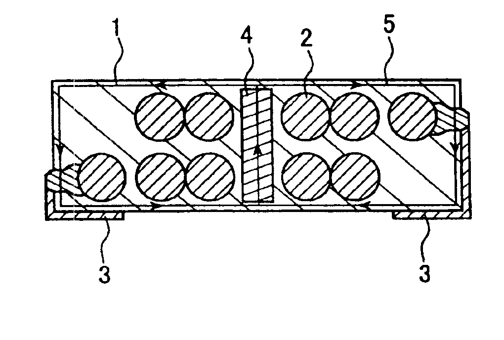
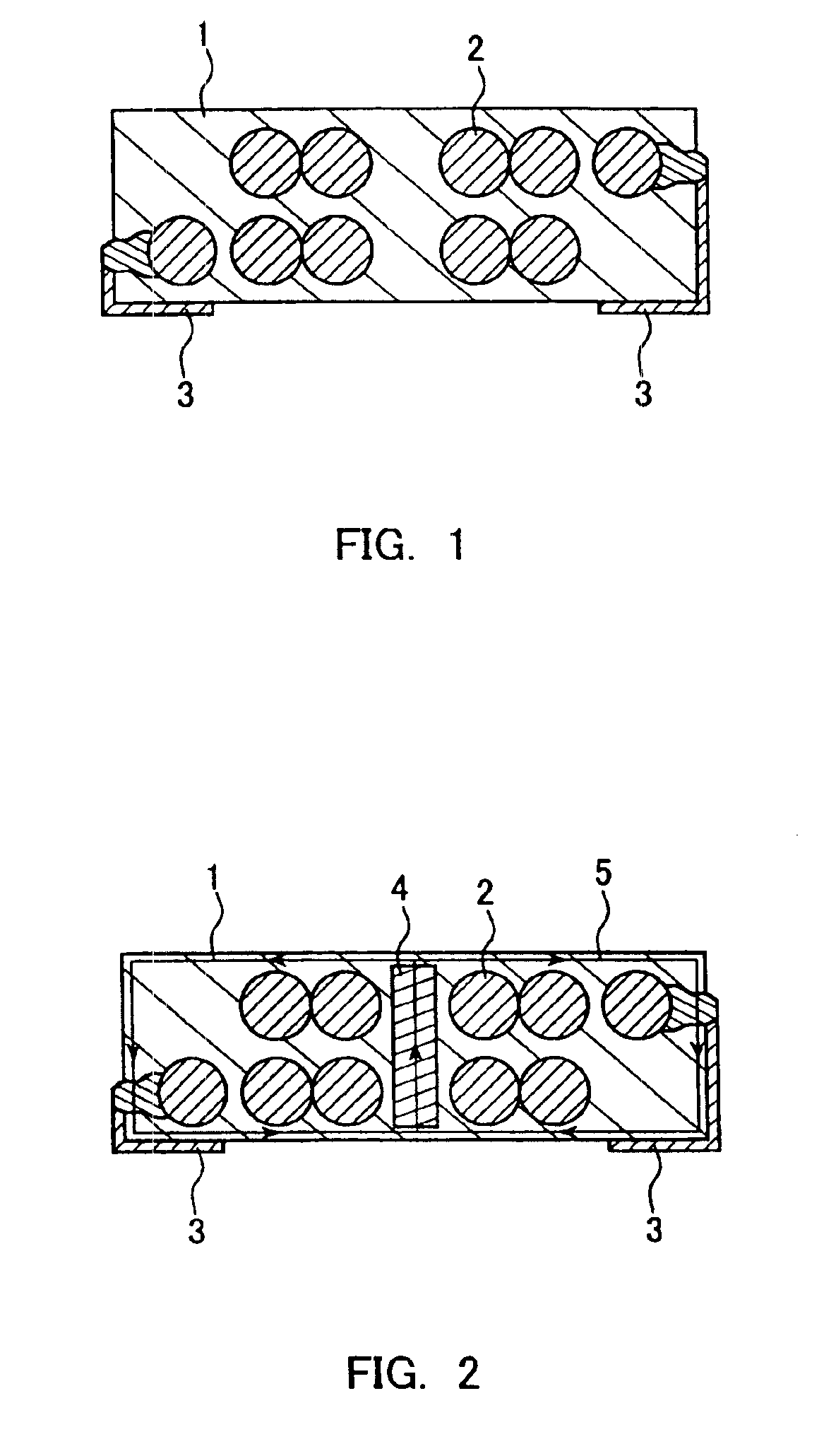
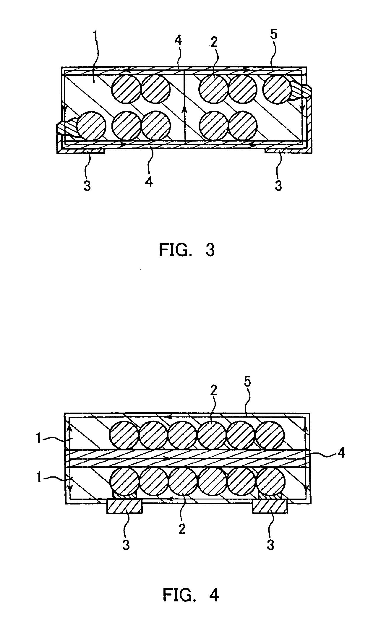
The present invention provides a composite magnetic body containing metallic magnetic powder and thermosetting resin and having a packing ratio of the metallic magnetic powder of 65 vol % to 90 vol % and an electrical resistivity of at least 104 Ω·cm. When a coil is embedded in this composite magnetic body, a miniature magnetic element can be obtained that has a high inductance value and is excellent in DC bias characteristics.

Description

[0001]This application is a divisional of application Ser. No. 09 / 843,258, filed Apr. 25, 2001, now U.S. Pat. No. 6,784,782, which application is incorporated herein by reference.BACKGROUND OF THE INVENTION[0002]1. Field of the Invention[0003]The present invention relates generally to a composite magnetic body, further to a magnetic element such as an inductor, a choke coil, a transformer, or the like. Particularly, the present invention relates to a miniature magnetic element used under a large current and a method of manufacturing the same.[0004]2. Related Background Art[0005]With the reduction in size of electronic equipment, the reduction in size and thickness of components and devices used therein also has been demanded strongly. On the other hand, LSIs such as a CPU are used at higher speed and have higher integration density, and a current of several amperes to several tens of amperes may be supplied to a power circuit provided in the LSIs. Hence, similarly in an inductor, si...

Claims


Application Information

Patent Timeline
Patent Type & Authority Patents(United States)
IPC IPC(8): H01F1/28H01F1/12H01F41/02H01F41/12H01F27/02H01F1/24H01F17/04H01F1/26H01F1/33
CPCH01F1/24H01F1/28H01F27/027H01F41/0246H01F41/127H01F1/26Y10T29/49277H01F17/04H01F27/292Y10S156/922Y10T29/4902Y10T29/49071Y10T156/1082Y10T29/49176Y10T428/32Y10T428/11Y10T29/49002Y10T29/4922Y10T29/49172Y10T156/11Y10T29/49158Y10T29/49021Y10T29/49073Y10T29/49261H01F1/00
Inventor INOUE, OSAMUKATO, JUNICHIMATSUTANI, NOBUYAFUJII, HIROSHITAKAHASHI, TAKESHI
Owner PANASONIC CORP
Why Eureka
Try Eureka