Modulated scatterometry

a scatterometer and module technology, applied in the field of improved scatterometer system, can solve the problems of difficult real-time evaluation of these calculations, complex task of theoretical model evaluation, and inability to fully realize the effect of theoretical model evaluation, and achieve the effect of improving the performance of an off-axis ellipsometer based scatterometer, improving the spatial resolution of measurement, and improving the performance of the off-axis ellipsometer

Inactive Publication Date: 2005-05-03
THERMA WAVE INC
View PDF21 Cites 41 Cited by
  • Summary
  • Abstract
  • Description
  • Claims
  • Application Information

AI Technical Summary

Benefits of technology

[0015]It may also be possible to use this approach to improve the spatial resolution of the measurement. For example, many existing scatterometers use a broadband source to generate a polychromatic probe beam. Measurements are taken as a function of wavelength. Unfortunately, it is difficult to focus a polychromatic probe beam to the extremely small spot sizes desired by the semiconductor industry. On the other hand, a narrow wavelength beam from a laser can be focused to significantly smaller spot. A beam from a laser could be modulated and used as the pump beam and focused to spot size well within the spot size of the polychromatic probe beam spot. The phase synchronous detection of the scattered light would then correspond to the information generated from the much smaller region illuminated by the pump source. In this way, the spatial resolution could be enhanced while still permitting detection at multiple wavelengths.
[0016]Use of a normal incidence, tightly focused pump beam can also improve the performance of an off-axis ellipsometer based scatterometer. As noted above, scatterometers systems can have an ellipsometer configuration where the probe beam is directed to the sample at a non-normal angle of incidence. Such an orientation causes the spot size of the beam to elongate. As noted above, by using a tightly focused modulated pump beam, the spatial resolution of the measurement can be enhanced. Beyond that, the normal incidence pump beam can be used to illuminate narrow open structures such as contact holes or vias.

Problems solved by technology

Evaluation of the theoretical models is a complex task, even for relatively simple structures.
As the models become more complex (particularly as the profiles of the walls of the features become more complex) the calculations can become extremely time consuming.
Even with high-speed processors, real-time evaluation of these calculations can be difficult.
This use of interpolation avoids the penalty associated with generating results in real-time, but may sacrifice accuracy during the interpolation process.

Method used


Image

  • Modulated scatterometry
  • Modulated scatterometry

Examples


Embodiment Construction

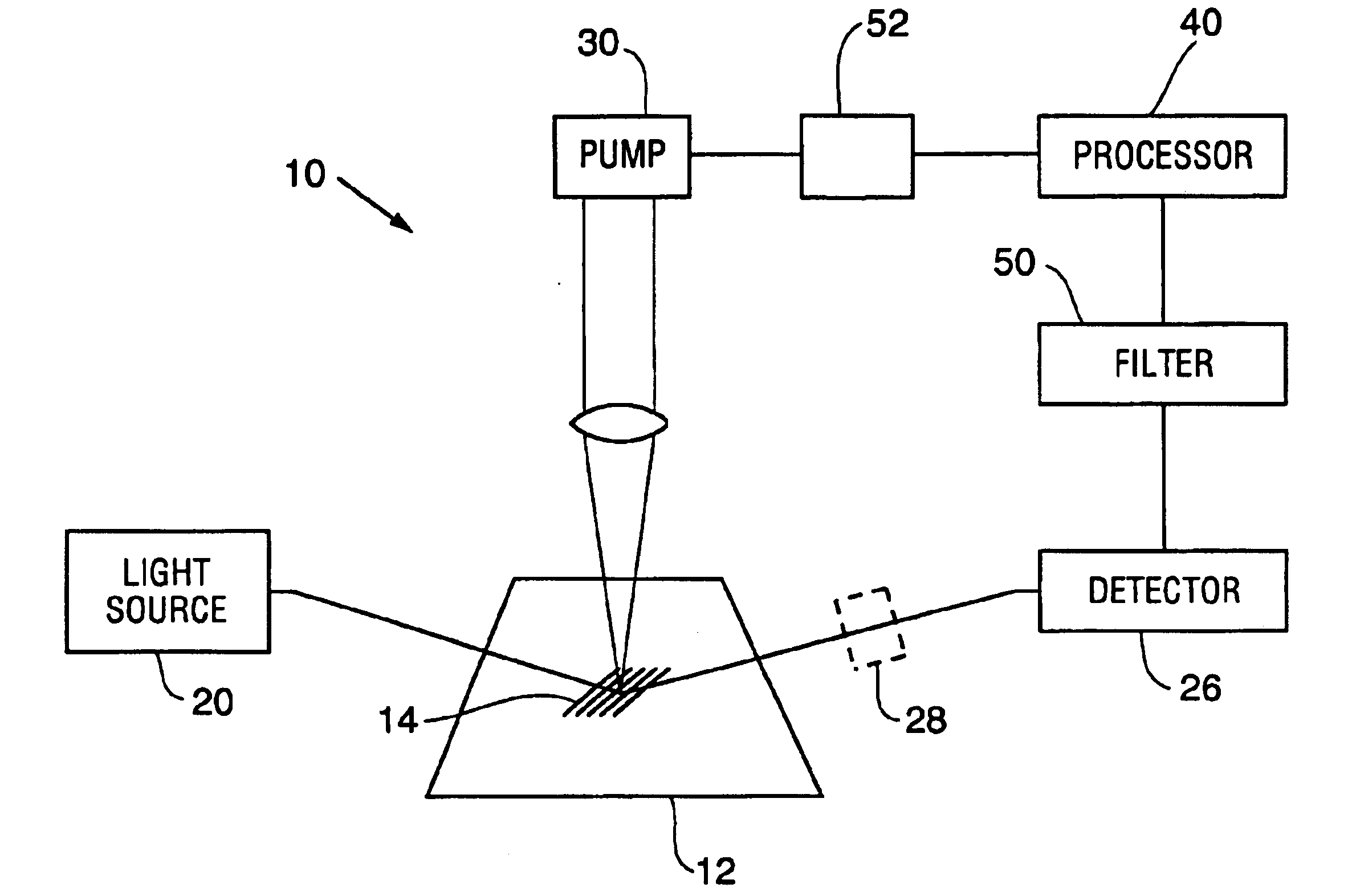
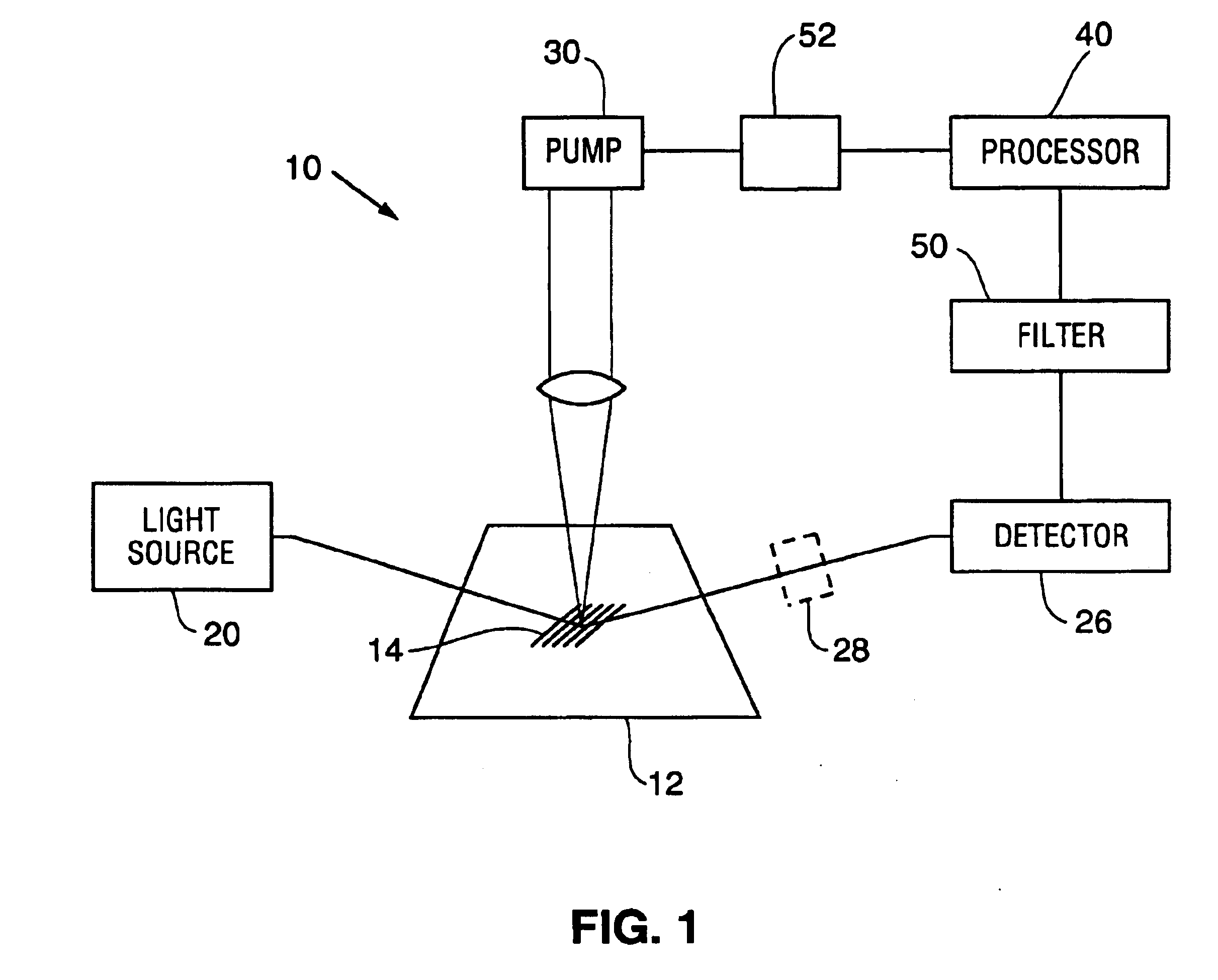
[0026]FIG. 1 illustrates a basic form of a scatterometry system 10 of the subject invention. The system 10 is intended to be used to perform evaluations of the type associated with prior scatterometers. For example, scatterometers have been used to evaluate a sample 12 having a periodic pattern of lines 14 formed thereon. The evaluation includes determining features such as height, spacing, side wall angle and shape. As noted above, scatterometers have also been used for to evaluate three dimensional features as well as for monitoring etching, dishing, planarity of a polished layer, control of gate electrode profiles, film stack fault detection, stepper control, deposition process control and resist thickness control

[0027]The subject scatterometers includes a light source 20 for of generating a probe beam of radiation 22. The light source is typically either a laser or a broad band or white light source for generating a polychromatic probe beam. The probe beam is directed to reflect...


PUM

PropertyMeasurementUnit
optical scatteringaaaaaaaaaa
function of wavelengthaaaaaaaaaa
phase synchronous detectionaaaaaaaaaa

Abstract

An apparatus for scatterometry measurements is disclosed. The apparatus includes a modulated pump source for exciting the sample. A separate probe beam is directed to interact with the sample and the modulated optical response is measured. The measured data is subjected to a scatterometry analysis in order to evaluate geometrical sample features that induce light scattering.

Description

TECHNICAL FIELD[0001]The subject invention relates to an improved scatterometry system which includes a modulated excitation source and a phase synchronous detection system to provide enhanced measurement capabilities.BACKGROUND OF THE INVENTION[0002]Over the past several years, there has been considerable interest in using optical scatterometry (i.e., optical diffraction) to perform measurements associated with semiconductor fabrication. One area of great interest has been the critical dimension (CD) measurements of the lines and structures included in integrated circuits. Optical scatterometry has been used to analyze periodic two-dimensional structures (e.g., line gratings) as well as three-dimensional structures (e.g., patterns of vias or mesas). Scatterometry is also used to perform overlay registration measurements. Overlay measurements attempt to measure the degree of alignment between successive lithographic mask layers. (See, U.S. 2002 / 0158193, incorporated by reference) Sc...

Claims


Application Information

Patent Timeline
Patent Type & Authority Patents(United States)
IPC IPC(8): G01N21/17G01N21/47
CPCG01N21/4788G01N21/1717G01N2021/1719
Inventor SMITH, WALTER LEE
Owner THERMA WAVE INC
Why Eureka
Try Eureka