Material transport method

a material transport and material technology, applied in the direction of charging manipulation, lighting and heating apparatus, furniture, etc., can solve the problems of limiting the usefulness of materials, limiting the use of materials, and many drawbacks of the above-described system

Inactive Publication Date: 2005-05-10
AMKOR TECH SINGAPORE HLDG PTE LTD
View PDF65 Cites 36 Cited by
  • Summary
  • Abstract
  • Description
  • Claims
  • Application Information

AI Technical Summary

Benefits of technology

[0011]The present invention provides a controlled material transport system (MTS) for carrying materials to and from, for example, work stations, test equipment, and processing and assembly tools in a common facility. The system of the present invention can deliver and / or remove material or payloads (e.g., semiconductor chips carried in magazines) directly to and / or from processing and assembly tools using a highly integrated vehicle running on a simple passive track system. The MTS of the present invention can load / unload magazines from any processing tool that can be serviced vertically from above.

Problems solved by technology

Unfortunately, in this system the ability to pick or place material at a given point is greatly limited due to lack of positional control of the material when the system lowers it due to side swaying and / or twisting.
Further, most suspended transport systems fail to provide off-axis loading, which limits their usefulness.
The drawbacks to the above-described system are many.
Foremost, as illustrated in FIG. 1B, rail device T of the inline system can require two feet or more of floor space, which can present a total space penalty of up to 30% on most factory floors.
If the floor space includes clean room floor space, the cost associated with such a floor space penalty can be dramatically increased.
Moreover, the inline system is not flexible in routing so that service can only be provided along a straight path.
Thus, another drawback of most typical transport systems is that they are designed for rear loading and are thus not capable of chute loading.
Most transport systems are also typically not flexible enough to support cell-to-cell transport or functional layout.
Consequently, to implement a modern transport system in an existing factory may require the buying of new equipment and / or the making of expensive factory and equipment modifications.

Method used


Image

  • Material transport method
  • Material transport method
  • Material transport method

Examples


Embodiment Construction

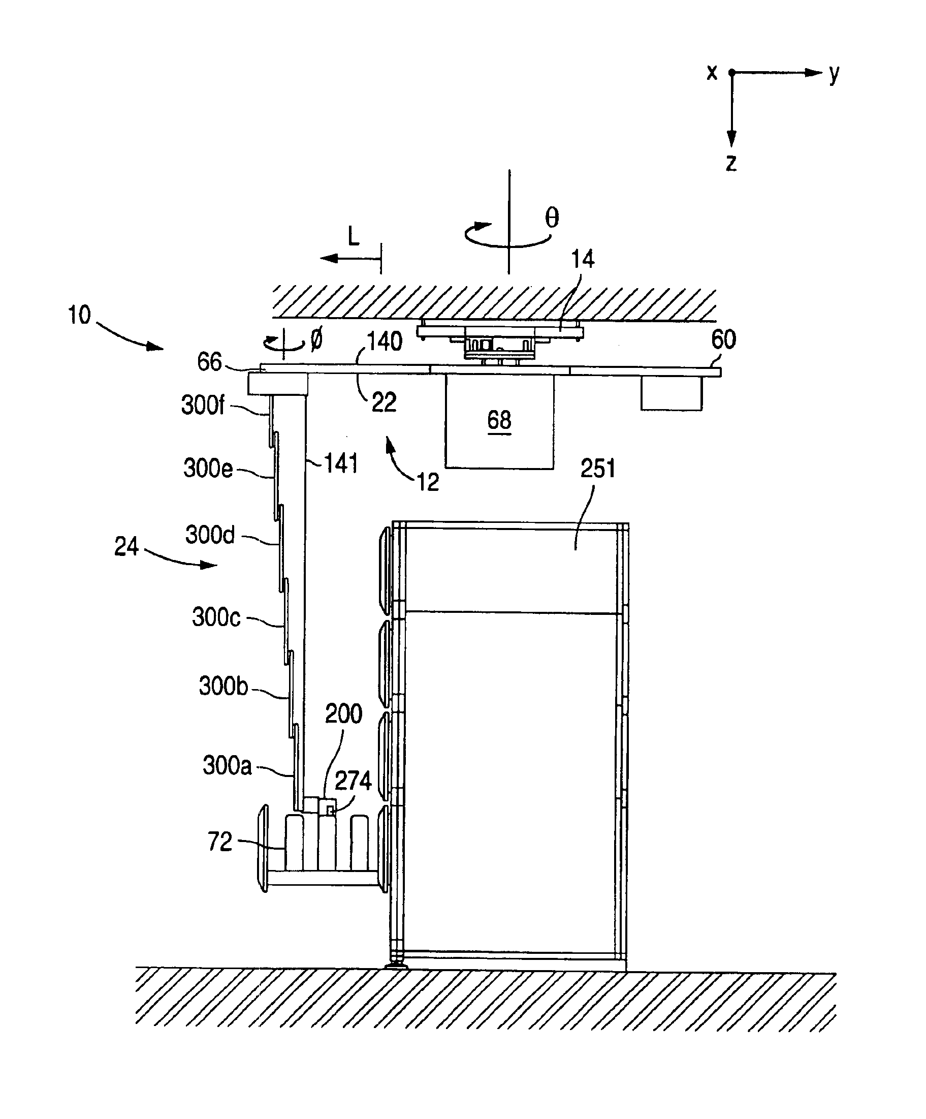
[0040]The material transport system (MTS) of the present invention is designed to transport materials or payloads to various locations in a plant, factory, or other common facility (hereinafter “factory”). The materials to be transported may be any materials or payloads, such as those that can undergo automatic processing and / or automatic treatment. Typically, the materials and payloads include semiconductor chip filled magazines (hereinafter “magazines”). As will be appreciated from the description that follows, with no intent to limit the invention thereby, the MTS is an overhead or ceiling mounted system for transporting magazines to FOL, BOL, and test equipment, such as die bonders, and / or wire bonders for establishing electrical connections on chips; continuous furnaces for the curing of plastics; and devices for the intermediate storage of the chips, backgrinders, tape cutters, and trim and form tools (hereinafter collectively “processing tools”). As an overhead system, the MT...


PUM


Abstract

A controlled material transport method for carrying materials to and from workstations, test equipment, and processing and assembly tools in a common facility. The present invention includes a rigid “robot vehicle” mountable to a passive track system, which can be routed to service all processing tools on the factory floor. The robot vehicle includes a hoist assembly and gripper assembly, which together perform such functions as picking up magazines, placing magazines, and loading magazines into the processing tools. The hoist assembly is capable of functioning in an operational envelope, which includes any target location within a 3-axis Cartesian coordinate system, to the extent of the range of motion of the hoist assembly. The hoist assembly also provides rigid and controlled z-axis travel, while being compact when retracted. The gripper assembly facilitates loading of the magazines, especially chute style magazines, which are commonly found on many existing processing tools.

Description

BACKGROUND OF THE INVENTION[0001]1. Field of the Invention[0002]The present invention generally relates to a material handling system, and more particularly, to a controlled system for moving materials to various locations within a manufacturing facility.[0003]2. Description of the Related Art[0004]To remain competitive in the manufacturing industry, manufacturers are constantly seeking out new ways to increase productivity. Advances in technology have helped to increase productivity by providing numerically controlled devices, which allow for the introduction of automated manufacturing equipment. One of the most significant advances in technology for increasing productivity has been the introduction of computers to the manufacturing floor. Computers have made it possible to accurately monitor and track production systems so manufacturers can adapt more quickly to production demands. Computers also facilitate the use of robots. Robots allow for the real-time adaptation of the manufa...

Claims


Application Information

Patent Timeline
Patent Type & Authority Patents(United States)
IPC IPC(8): B66F9/07H01L21/687H01L21/677H01L21/67
CPCB66F9/07H01L21/67706H01L21/67736H01L21/68707H01L21/67733Y10S414/14
Inventor TRAMMELL, HAROLD L.BOND, ROBERT H.
Owner AMKOR TECH SINGAPORE HLDG PTE LTD
Why Eureka
Try Eureka