
Catheters with fluorescent temperature sensors

a technology of temperature sensor and catheter, which is applied in the field of catheters with temperature sensors and catheters with fluorescent temperature sensors, can solve the problems of prognostic and diagnostic dilemma, rupture of atherosclerosis plaque, and injuring the heart or brain

Inactive Publication Date: 2005-05-10
BOSTON SCI SCIMED INC
View PDF45 Cites 52 Cited by
  • Summary
  • Abstract
  • Description
  • Claims
  • Application Information

AI Technical Summary

Benefits of technology

[0014]The present invention satisfies the aforenoted needs by provided an improved catheter temperature sensor and me

Problems solved by technology

However, in most instances of coronary disease, it is found that only one of the atherosclerotic plaques has ruptured, fissured, or ulcerated.
The rupture, fissure, or ulcer causes a large blood clot to form on the inside of the artery, which may completely occlude the flow of blood through the artery, thereby injuring the heart or brain.
A major prognostic and diagnostic dilemma for the cardiologist is how to predict which plaque is about to rupture.
Both patents disclose infrared devices and are not readily adaptable to existing catheter systems.

Method used


Image

  • Catheters with fluorescent temperature sensors
  • Catheters with fluorescent temperature sensors
  • Catheters with fluorescent temperature sensors

Examples


Embodiment Construction

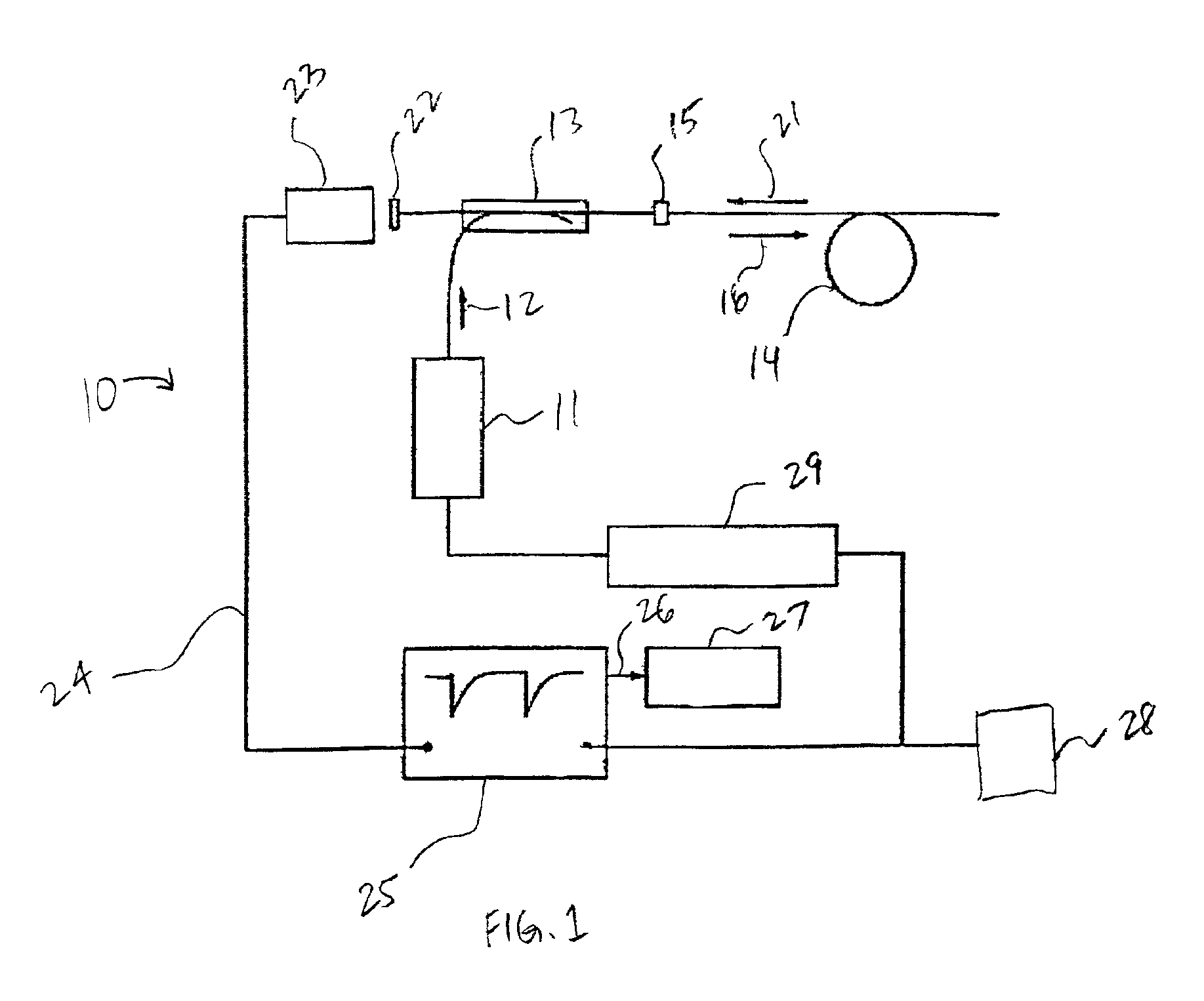
[0061]Phosphors consist of inorganic oxides, oxysulfides, orthophosphates and rare earth metals. Phosphors typically contain a small concentration of a dopant. When excited by certain wavelengths of light, phosphors will fluoresce and the decay time of the fluorescents is proportional to the temperature of the phosphor. As the temperature increases, typically, the decay time decreases for a particular emission wavelength.

[0062]Preferred phosphors used in the disclosed embodiments include manganese doped magnesium fluorogermanate and europium doped lanthanum oxysulfide. These phosphors have peak emission intensities at 514 nm, 538 nm and 619 nm.

[0063]In the embodiment illustrated in FIG. 1, the system 10 utilizes a light source 11, which is preferably a laser, more preferably a nitrogen laser. The light source 11 preferably emits ultraviolet light which is transmitted in the direction of the arrow 12 through a beam splitter 13. The beam splitter 13 is connected to a fiberoptic cable ...


PUM


Abstract

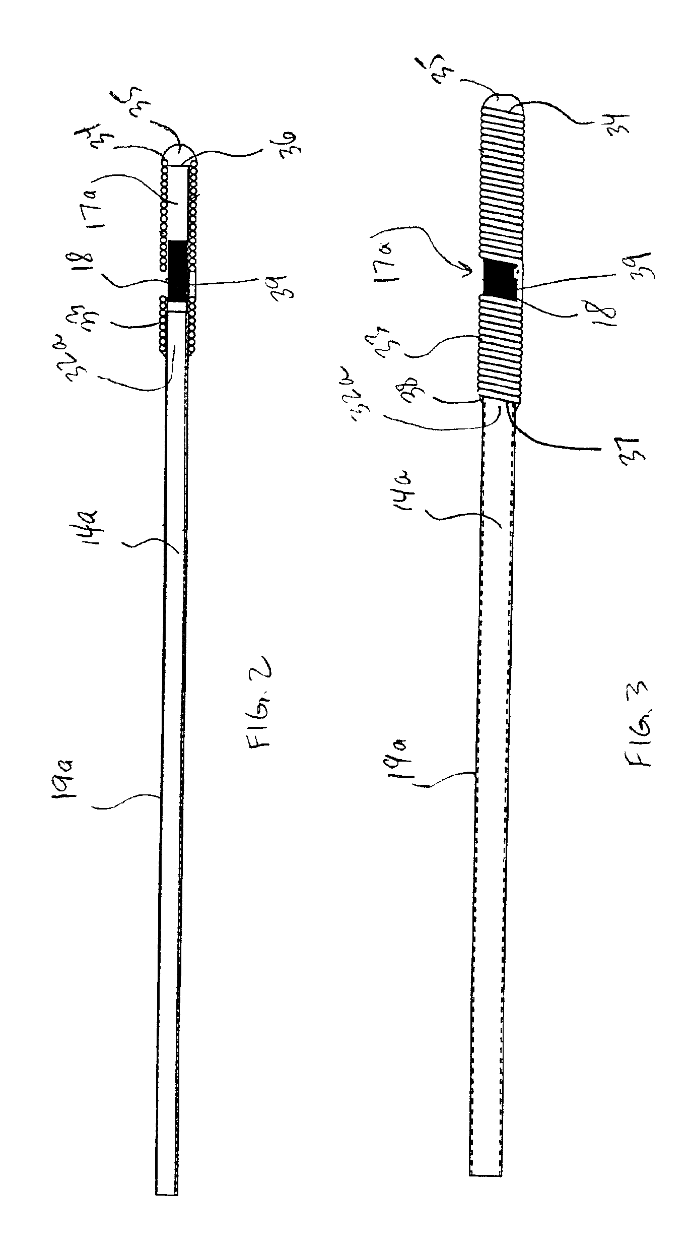
A catheter with a fluorescent temperature sensor is shown and described. The catheter includes a lumen, a fiber-optic cable that extends through the lumen. A distal end of the fiber-optic cable is coated with a fluorescent material and a proximal end of the fiber-optic cable is connected to a console. The console includes a light source for transmitting light through the fiber-optic cable for exciting the fluorescent material. The console further includes a photo multiplier tube for converting light emitted by the excited fluorescent material to a plurality of analog voltage signals. The console further includes a digital oscilloscope linked to the photo multiplier tube for converting the plurality of analog voltage signals to at least one digital signal. The console further includes a processor linked to the digital oscilloscope for converting the at least one digital signal to a temperature value for the distal end of the fiber-optic cable.

Description

CROSS-REFERENCE TO RELATED APPLICATION[0001]This application claims the benefit under 35 U.S.C. § 119(e) of U.S. provisional patent application Ser. No. 60 / 272,674 filed Mar. 1, 2001, the disclosure of which is incorporated herein by reference.FIELD OF THE INVENTION[0002]The present invention relates generally to the field of surgical catheters. More specifically, the present invention relates to surgical catheters with temperature sensors. Still more specifically, the present invention relates to catheters with fluorescent temperature sensors and methods of measuring temperatures along arterial walls using a catheter equipped with a fluorescent temperature sensor for detecting and locating inflamed plaque.BACK GROUND OF THE INVENTION[0003]Measuring the temperature of tissues, veins or other body parts at remote locations during surgical, electrophysiological and other invasive and minimally invasive procedures can provide critical information to the physician or surgeon. One such p...

Claims


Application Information

Patent Timeline
IPC IPC(8): A61B5/00A61B5/01
CPCA61B5/01A61B5/6885A61B5/6859A61B5/6853
Inventor KOKATE, JAYDEEP Y.DOBRAVA, ERIC M.SMITH, SCOTT R.
Owner BOSTON SCI SCIMED INC
Learn More