Dual-porosity ribbed fuel cell cathode

a fuel cell and rib-shaped technology, applied in the field of cathode, can solve the problems of creeping of the cathode, approximately 25% of the lithium carbonate in the electrolyte is depleted after 40,000, large amount of electrolyte loss of the fuel cell, etc., and achieves less porosity, less porosity, and greater thickness.

Inactive Publication Date: 2005-05-10
FUELCELL ENERGY INC
View PDF8 Cites 15 Cited by
  • Summary
  • Abstract
  • Description
  • Claims
  • Application Information

AI Technical Summary

Benefits of technology

[0013]In accordance with the principles of the present invention, the above and other objectives are realized in a fuel cell cathode comprising a cathode body having rib regions and base regions which connect the rib regions, the rib regions being of greater thickness and of less porosity than the base regions. With this type of construction, the lower porosity of the rib regions permits these regions to be more compacted so as to provide the needed strength for the cathode to withstand compressive forces and avoid creep. The higher porosity of the base regions, in turn, enhances fuel cell performance.

Problems solved by technology

The conventional cathode assembly results in a large amount of electrolyte loss from the fuel cell.
It has been experimentally determined that approximately 25% of the lithium carbonate in the electrolyte is depleted after 40,000 hours of operation due to corrosion of the current collector of the assembly.
Because fuel cells operate under a constant compressive load, another difficulty experienced with the conventional fuel cell cathode assembly is creep of the cathode.
In spite of these advantages, the increased thickness of the ribbed cathode makes it more susceptible to cathode creep.
As above-mentioned, the ribbed cathodes formed by these procedures still exhibit significant creep in the absence of strengthening additives.

Method used


Image

  • Dual-porosity ribbed fuel cell cathode
  • Dual-porosity ribbed fuel cell cathode
  • Dual-porosity ribbed fuel cell cathode

Examples


example

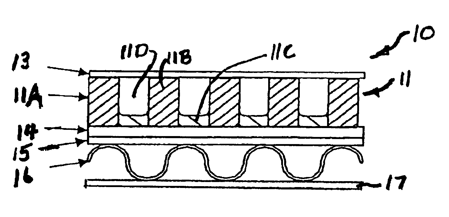
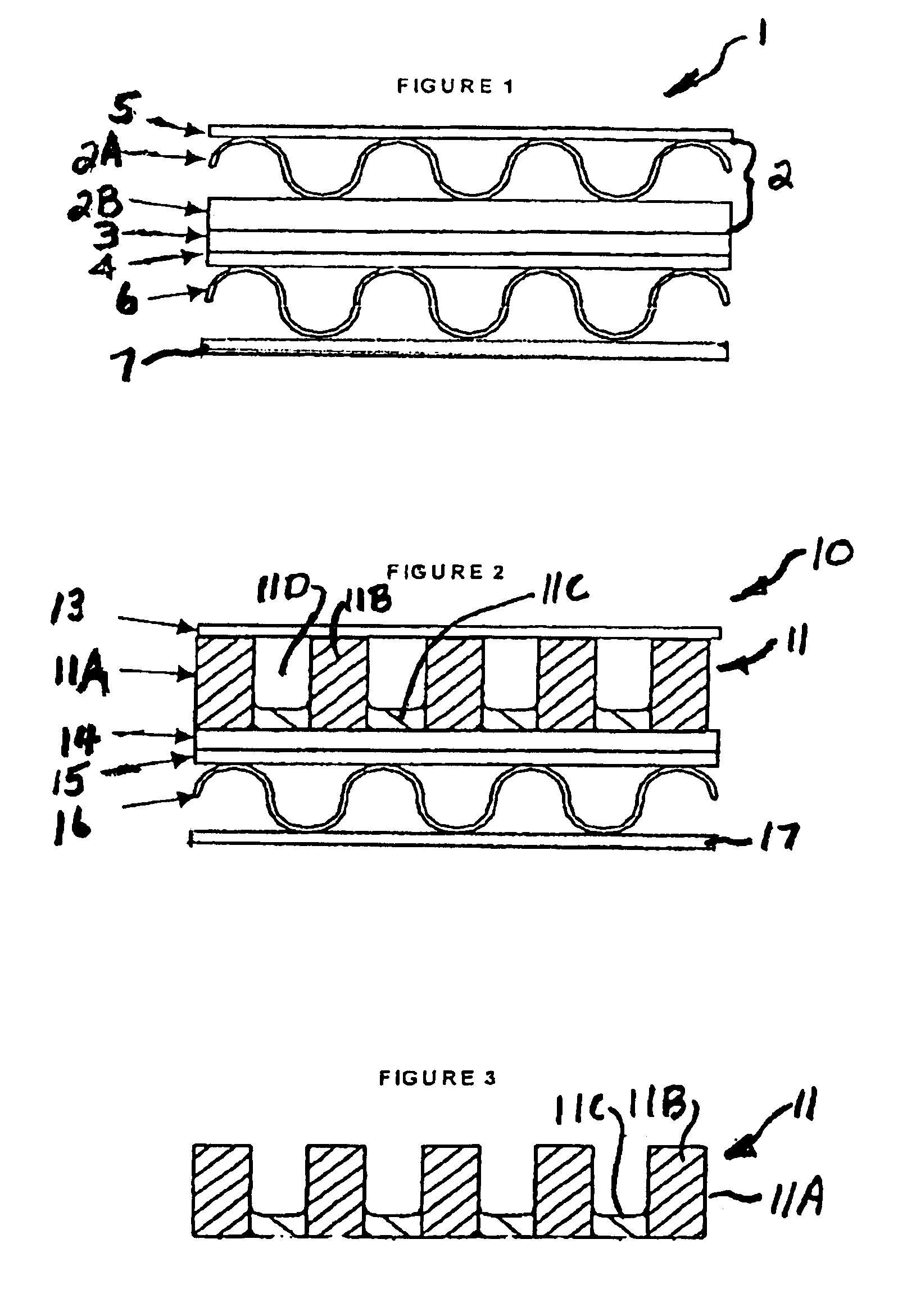
[0043]A cathode in accordance with the principles of the present invention was fabricated by dry doctoring INCO 287 nickel filamentaxy powder onto a graphite substrate and sintering the powder bed at approximately 810° C. for approximately 10 minutes in a tunnel furnace in a reducing atmosphere. After sintering, the planar cathode was pinch-rolled to a porosity of 75% and a thickness of 105 mil. Channels were then machined into the flat, sintered sheet to form ribs. In practice, the ribs may be formed in a mold to attain faster production speeds. Cross-slits or cutouts were then machined perpendicular to the rib direction every ¾ inch to allow for gas communication between the channels. The rib and channel widths were each approximately 50 mil.

[0044]After the ribs were machined, the cathode was pinch-rolled to consolidate the height and reduce the rib area porosity from 75% to 72%, while leaving the material between the ribs at 75% porosity. The cathode was then filled with electrol...


PUM

PropertyMeasurementUnit
porosityaaaaaaaaaa
porosityaaaaaaaaaa
thicknessaaaaaaaaaa

Abstract

A fuel cell cathode comprising a cathode body having rib regions and base regions which connect the rib regions, the rib regions being of greater thickness and of less porosity than the base regions.

Description

STATEMENT REGARDING FEDERALLY SPONSORED RESEARCH OR DEVELOPMENT[0001]This invention was made with Government support under Contract No. DE- FG02-95ER81966 awarded by the U.S. Department of Energy. The Government has certain rights in this invention.BACKGROUND OF THE INVENTION[0002]This invention relates to a cathode for carbonate fuel cells and, in particular, to a ribbed cathode for such cells.[0003]Carbonate fuel cells produce energy in a clean and efficient way by directly converting chemical energy stored in hydrocarbon fuel into electrical energy by means of an electrochemical reaction. Generally, a fuel cell unit comprises an anode and a cathode separated by an electrolyte, which serves to conduct electrically charged ions. In carbonate fuel cells, reactant fuel gas is passed through the anode, while oxidizing gas is passed through the cathode. In order to produce a useful power level, a number of individual fuel cell units are stacked in series with an electrically conductive...

Claims


Application Information

Patent Timeline
Patent Type & Authority Patents(United States)
IPC IPC(8): H01M4/88H01M4/90H01M8/24H01M4/86H01M8/14H01M8/02
CPCH01M4/8621H01M4/8885H01M4/90H01M8/244H01M8/142H01M8/145H01M8/0202H01M8/0258Y02E60/50H01M8/2459
Inventor JOHNSEN, RICHARDYUH, CHAO-YIALEXANDER, MICHAEL
Owner FUELCELL ENERGY INC
Why Eureka
Try Eureka