Plasma processing method using spectroscopic processing unit

Inactive Publication Date: 2005-05-10
HITACHI LTD +1
View PDF28 Cites 6 Cited by
  • Summary
  • Abstract
  • Description
  • Claims
  • Application Information

AI Technical Summary

Benefits of technology

[0008]On the other hand, in the plasma processing apparatus, the incident radiation quantity may change remarkably (ca. ten times or more) due to aged contamination of a process chamber. For coping with such change of the incident radiation quantity, it is not preferred to change the charge storing time of the CCD array because then the operation timing of the whole system will have to be changed remarkably. Further, in the spectrum of plasma emission produced in the plasma processing apparatus, there are coexistent mixedly a plurality of high luminance portions exhibiting steep peaks and low luminance portions changing relatively gently as a function of the wavelength (see e.g. U.S. Pat. No. 6,261,470B1, FIG. 17A or European Patent No. 1089146, FIG. 3C). In the applications where the emission spectra are detected by using the CCD array, setting of the amplification factor for the output signal of the CCD array so that no saturation can occur at the steep peaks will inevitably be accompanied with remarkable degradation of the S / N ratio for the low luminance portion of the radiation. On the contrary, when the amplification factor is set in conformance with the low luminance portion, saturation will easily occur in the peak portions.
[0010]In the light of the state of the art described above, it is an object of the present invention to provide an emission spectroscopic processing apparatus which is capable of detecting minute changes in emission spectra of high rate or speed on the order of one second or less with enhanced or improved reproducibility.

Problems solved by technology

However, in the CCD array which is constituted by a large number of integrated light receiving elements, such a problem is encountered that when the light receiving elements each of small capacity are employed in an effort to increase the sensitivity, then noise also increases, whereas when the light receiving elements of large capacity are employed with a view to suppressing the noise, the sensitivity of the CCD array will become lowered.
This problem is not inherent to the CCD array but generally common to photosensor devices each composed of a large number of integrated light receiving elements.
However, in the case where the CCD array or the like device is used as the means for detecting the emission spectra, the signal which can be made available is very poor in respect to the S / N ratio as mentioned previously.
However, with this method, it is necessary to repetitively perform the addition of a sample one hundred times or more if the signal-to-noise ratio is to be increased by one order of magnitude.
Such processing will ordinarily require several to several ten seconds, which in turn renders it relatively difficult to detect the minute change (change of less than 10% or so) of high rate or speed on the order of one second or 0.5 second or lower in terms of temporal duration.
In particular, in a low luminance portion which changes relatively gently as a function of the wavelength in the emission spectra such as of plasma, great difficulty will be encountered in detecting the minute change of high rate on the order of one second or less with satisfactory reproducibility.

Method used


Image

  • Plasma processing method using spectroscopic processing unit
  • Plasma processing method using spectroscopic processing unit
  • Plasma processing method using spectroscopic processing unit

Examples


Embodiment Construction

[0027]The present invention will be described in detail in conjunction with what is presently considered as preferred or typical embodiments thereof by reference to the drawings. In the following description, like reference characters designate like or corresponding parts throughout the several views.

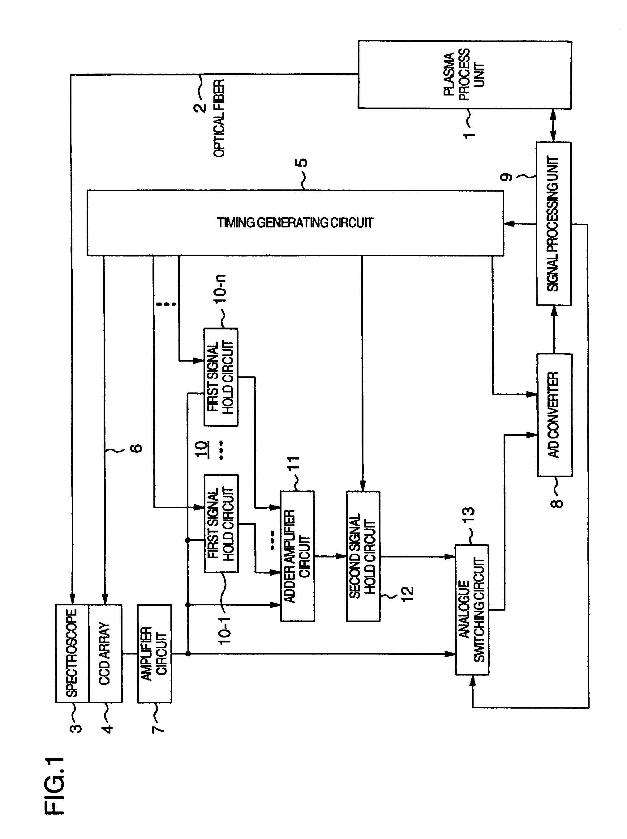
[0028]FIG. 1 is a block diagram showing schematically and generally a structure of the emission spectroscopic processing apparatus according to an embodiment of the present invention. Referring to the figure, plasma emission produced within a treatment or process chamber of a plasma process unit 1 is introduced as input light into a spectroscope 3 through the medium of an optical fiber 2 via a slit. The spectroscope 3 serves for spectrally separating the input light passed through the slit into component spectra covering angles mutually differing on a wavelength-by-wavelength basis. The component spectra resulting from the spectral separation mentioned above then impinge onto a CCD (Cha...


PUM

PropertyMeasurementUnit
Wavelengthaaaaaaaaaa

Abstract

A plasma processing method using a spectroscopic processing unit. The method includes separating spectrally plasma radiation emitted from a vacuum process chamber into component spectra, converting the component spectra into a time series of analogue electric signals composed of different wavelength components at a predetermined period, adding together analogue signals of the different wavelength components, converting a plurality of added signals into digital quantities on a predetermined-period basis, digitally adding together the plurality of added and converted signals a plural number of times on a plural-signal basis, determining discriminatively an end point of a predetermined plasma process on the basis of a signal resulting from the digital addition, and terminating the predetermined plasma process.

Description

CROSS-REFERENCE TO RELATED APPLICATION[0001]This is a divisional of U.S. application Ser. No. 10 / 090,759, filed Mar. 6, 2002, now U.S. Pat. No. 6,716,300, the subject matter of which is incorporated by reference herein, and the present invention is related to (1) U.S. patent application Ser. No. 09 / 793,624 filed Feb. 27, 2001, (2) U.S. patent application Ser. No. 09 / 797,601 filed Mar. 5, 2001 and (3) U.S. patent application Ser. No. 09 / 946,504 filed Sep. 6, 2001.BACKGROUND OF THE INVENTION[0002]The present invention relates generally to an emission spectroscopic processing apparatus for spectrally separating radiation emitted from a plasma or the like into component spectra, converting the component spectra having respective wavelengths into electric signals by means of associated light receiving elements, respectively, and obtaining a desired detection output by processing the signals. Further, the present invention relates to a plasma processing method using the emission spectrosc...

Claims


Application Information

Patent Timeline
IPC IPC(8): G01N21/71G01N21/73H01J37/32G01L21/30
CPCG01L21/30H01J37/32972H01J37/32935G01N21/73
Inventor KAJI, TETSUNORIKIMURA, SHIZUAKIUSUI, TATEHITOFUJII, TAKASHI
Owner HITACHI LTD
Why Eureka
Try Eureka