Thermal recording materials

a technology of thermal recording materials and thermal recording materials, which is applied in the direction of thermography, instruments, photosensitive materials, etc., can solve the problems of insufficient light resistance in storage, low thermal response, and inability to say that thermal recording materials are satisfactory, etc., to achieve excellent thermal response, excellent whiteness, and excellent heat resistance of ground and images.

Inactive Publication Date: 2005-05-10
MITSUBISHI PAPER MILLS LTD
View PDF14 Cites 6 Cited by
  • Summary
  • Abstract
  • Description
  • Claims
  • Application Information

AI Technical Summary

Benefits of technology

[0009]Under the circumstances, it is a first object of the present invention to provide a thermal recording material excellent in thermal response, heat resistance of ground and images and light resistance in storage, and it is a second object of the present invention to provide a thermal recording material excellent in whiteness.

Problems solved by technology

However, the thermal recording materials are not satisfactory with regard to heat resistance in storage in an environment at 100° C. and also have low thermal response.
However, it cannot be said that sufficient light resistance in storage can be obtained.

Method used


Image

  • Thermal recording materials
  • Thermal recording materials
  • Thermal recording materials

Examples


preparation example 1

[0097]Preparation of Dispersions A to J

[0098]<Dispersion A>

[0099]200 Grams of 3-(N-ethyl-N-tolyl)amino-6-methyl-7-anilinofluorane was dispersed in a mixture of 200 g of a 10 wt % sulfone-group-modified polyvinyl alcohol aqueous solution with 600 g of water, and the resultant mixture was pulverized with a beads-applied mill until the mixture had an average particle diameter of 1 μm, to give Dispersion A.

[0100]<Dispersion B>

[0101]200 Grams of 3-dibutylamino-6-methyl-7-anilinofluorane was dispersed in a mixture of 200 g of a 10 wt % sulfone-group-modified polyvinyl alcohol aqueous solution with 600 g of water, and the resultant mixture was pulverized with a beads-applied mill until the mixture had an average particle diameter of 1 μm, to give Dispersion B.

[0102]<Dispersion C>

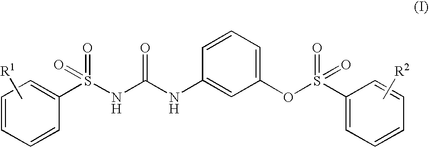
[0103]200 Grams of 3-(p-toluenesulfonyl)-N′-(3-p-toluenesulfonyloxyphenyl)urea was dispersed in a mixture of 200 g of a 10 wt % sulfone-group-modified polyvinyl alcohol aqueous solution with 600 g of...

example 1

(1) Preparation of Thermal Recording Layer Coating Solution

[0118]Some of Dispersions obtained in Preparation Example 1 and other materials were mixed in amounts shown below, water was added to the mixture to form an aqueous solution having a thermal recording layer coating concentration of 15% by weight, and the resultant mixture was fully stirred to give a thermal recording layer coating solution.

[0119]

Dispersion A30 partsDispersion C70 partsDispersion D 7 partsDispersion J50 parts40 wt % Zinc stearate dispersion10 parts10 wt % Completely saponified polyvinyl40 partsalcohol (PVA) aqueous solution

(2) Preparation of Thermal Recording Material Substrate

[0120]An undercoat layer coating solution having the following composition was applied onto wood-free paper having a basis weight of 40 g / m2 so as to form a coating having a coating weight of 10 g / m2, and the applied coating solution was dried to obtain a thermal recording material substrate.

[0121]

Calcined kaolin100 parts50 wt % Styrene...

example 2

[0123]A thermal recording material was obtained in the same manner as in Example 1 except that Dispersion G in an amount shown below was added to the thermal recording layer coating solution in Example 1.

[0124]

Dispersion G1 part


PUM

PropertyMeasurementUnit
temperatureaaaaaaaaaa
heat resistanceaaaaaaaaaa
melting pointaaaaaaaaaa

Abstract

Disclosed are a thermal recording material having a thermal recording layer containing an electron-donating dye precursor and an electron-accepting compound, wherein the thermal recording layer comprises an electron-accepting compound of the general formula (I), (each of R1 and R2 is a hydrogen atom or an alkyl group), and a specific aromatic phosphorus compound, and a thermal recording material wherein said thermal recording layer comprises the electron-accepting compound of the above general formula (I) and an undercoat layer formed on a substrate comprises an organic pigment having a specific morphological structure.The former thermal recording material is excellent particularly in thermal response as well as heat resistance and light resistance of a ground and images in storage, and the latter thermal recording material is excellent particularly in whiteness.

Description

[0002]This application is a U.S. national stage of International Application No. PCT / JP01 / 07712 filed Sep. 5, 2001.TECHNICAL FIELD[0003]The present invention relates to a thermal recording material, and more specifically to a thermal recording material excellent in thermal response, heat resistance of ground and images and light resistance in storage or a thermal recording material excellent in whiteness.TECHNICAL BACKGROUND[0004]Generally, thermal recording materials are obtained by forming a thermal recording layer on a substrate, and the thermal recording layer contains an electron-donating generally colorless or light-colored dye precursor and an electron-accepting developer as main components. Thermal recording materials give an image to be recorded by an instant reaction between the dye precursor and the developer upon heating with a thermal head, a thermal pen or a laser beam. The above thermal recording materials have advantages that a recording is obtained with a relatively...

Claims


Application Information

Patent Timeline
Patent Type & Authority Patents(United States)
IPC IPC(8): B41M5/40B41M5/333B41M5/42B41M5/30B41M5/327B41M5/337
CPCB41M5/3333B41M5/426B41M5/3275B41M5/3375B41M5/3336
Inventor TSUKADA, HIDETAKA
Owner MITSUBISHI PAPER MILLS LTD
Why Eureka
Try Eureka