Pure aluminum does not make driveshaft components of acceptable strength, but alloys of aluminum have adequate strength.
While aluminum alloys have been an acceptable material because of their strength and lighter weight, problems have been experienced using conventional
welding techniques with such components.
For example, aluminum components have been weakened by heat generated and transferred to them during conventional
welding.
However, these attachment methods are not as economical as desired, particularly when applied to driveshafts of vehicles.
Unfortunately, the results of such a method for attaching end fittings to driveshaft tubes have been less than satisfactory.
Aluminum, which is typically used in driveshafts, is a notch sensitive material, and is subject to
cracking where it is stressed by being deformed into shapes having relatively large contours.
Also, when torque is applied to the driveshaft in the vehicle, there is a small amount of slippage between the yoke and the driveshaft tube which produces a loud and irritating sound.
This has resulted in a large number of
consumer complaints.
But with a high level of torque, as measured with fatigue tests, the life of the driveshaft is reduced considerably.
Unfortunately, all of these have been unsatisfactory.
Further, conventional MPW apparatus is not capable of
magnetic pulse welding of end fittings with driveshafts made from high-strength aluminum alloys like 6061T.
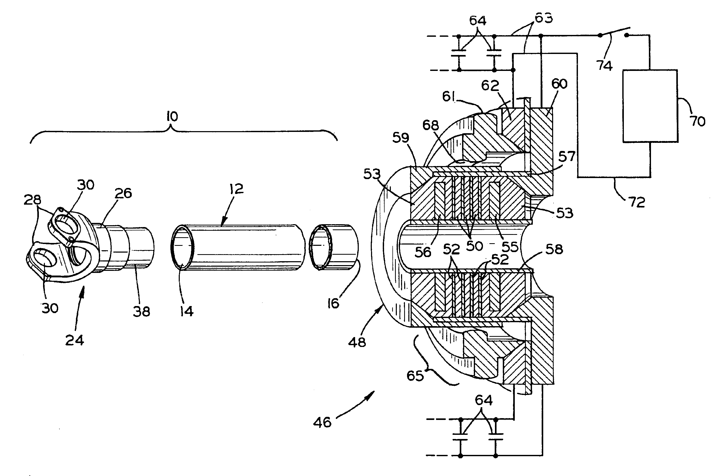
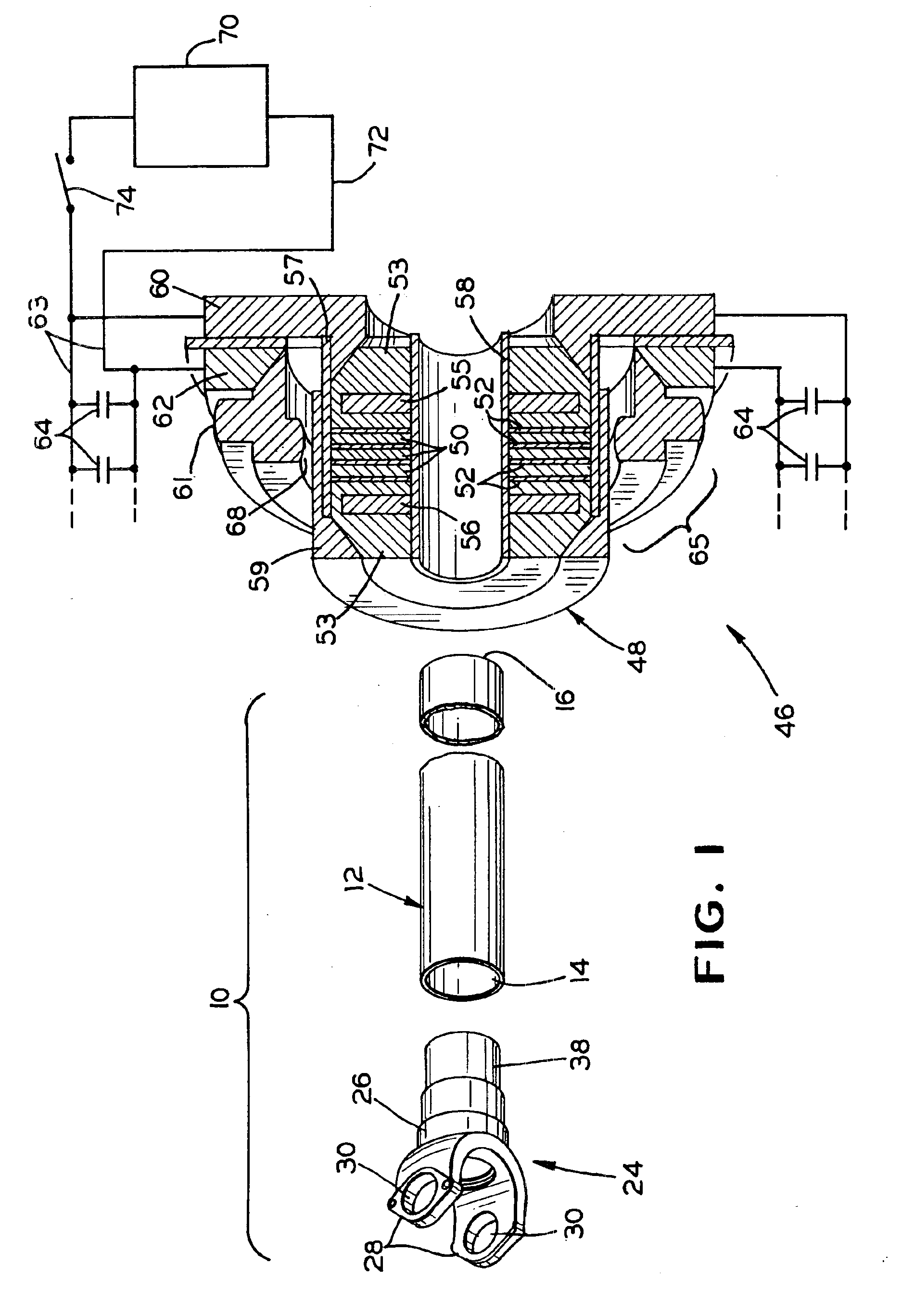
In principle, AMPE should permit tubes as large as a driveshaft to be welded using MPW, but there appear four problems which must be solved before this technology can become valuable from a manufacturing point of view.
The first problem is the destruction and
contamination of insulation elements of
inductor by the powerful cumulative jet which flows axially along the
welding surfaces (i.e., axially of the driveshaft tube) during the
welding process.
The second problem is the low strength of the
welding joint between high-strength aluminum
alloy tubes and the end fitting if the latter is made from steel.
The third problem is the possibility of premature breakdown of the
vacuum switch.
And the fourth problem is a long
cycle time and resulting low productivity of AMPE.
The last two problems are connected and contradictory to each other.
If the cumulative jet is restrained, and reflected from obstacles such as the shoulder of the end fitting or the surfaces of tooling, and directed toward the insulation elements of inductor, then the cumulative jet can create problems.
In such a case, the insulation elements can be contaminated and can be destroyed within a short number (perhaps less than 100) of welding cycles.
Obviously this is unacceptable in a manufacturing process because breakdown of the inductor is possible.
As a result of the problems described above, welding using MPW has not yet been found to produce high quality welding joints between driveshaft tubes and end fittings if the driveshaft tubes are made from high-strength aluminum alloys like 6061 and any related temper, and the end fittings are made from middle carbonic steel like EMS-40.
The problem of eliminating the aforementioned self breakdown of the switch is a basic problem in the technique of high
pulse current and strong magnetic fields.
This problem becomes especially complicated if the amplitude of the current achieves a level of one
mega-
ampere or more, if the energy of the pulse is 40 kilojoules or more, if the charge transfer is 10 coulombs or more, and if the frequency of pulses more than one per minute.
But the failure of the
magnetic pulse welding operation cannot be corrected by using repetition of the
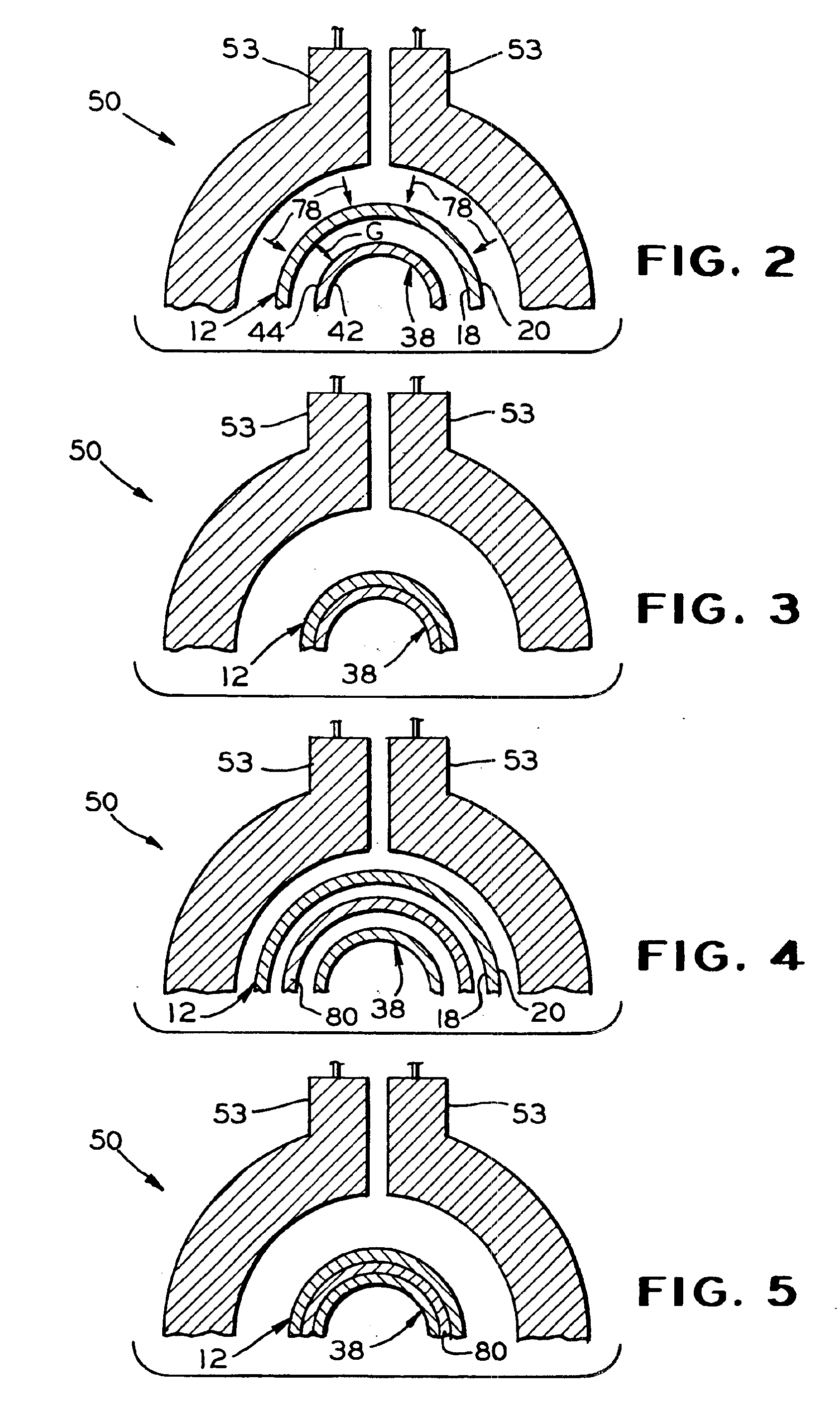
discharge pulse because the first pulse changes or eliminates the gap between the welded surfaces, the value of which is very critical for the success of the MPW process.
Failure of MPW results in an irrecoverably useless driveshaft tube.
The first has a massive high-strength single-turn coil, the
disadvantage of which is a gap between the leads, resulting in a nonuniform magnetic force field, and thereby providing a non-uniform weld.
The higher the amplitude of the current and the higher the energy of the pulse, the more complicated become the problems of switching that current's pulse.
This problem becomes more and more complicated if the
pulse current must be repeated with short intervals, as is necessary in an economical manufacturing process.
It provides 2.0 to 2.5 current discharges in a minute, but this is not enough for economical manufacturing of driveshafts.
Unfortunately, this relation is true only if intervacuum surfaces of insulation elements are clean.
As a result of the deposition of these products of
erosion on the elements of the
vacuum switch, the switch is not capable of blocking the
voltage developed across the
capacitor bank if the charging starts too early.
However, part of the metallic vapors and drops are deposited on surfaces of the insulators, and over time they form a
coating on various insulating elements, and this consequently decreases the insulating properties.
But experiments found that a good vacuum in the
discharge chamber is not sufficient by itself to prevent premature discharge.
An additional
disadvantage of the AMPE is that there is no guarantee that each cycle will work properly because a self breakdown is possible.
The disadvantages of this solution are the sophisticated and
large size required for the disconnectors.



