Refractive projection objective with a waist

a projection objective and waist technology, applied in the field of projection systems, can solve the problems of significant higher cost and less availability of calcium fluoride than quartz glass, and achieve the effect of improving the longitudinal chromatic aberration

Inactive Publication Date: 2005-05-10
CARL ZEISS SMT GMBH
View PDF13 Cites 138 Cited by
  • Summary
  • Abstract
  • Description
  • Claims
  • Application Information

AI Technical Summary

Benefits of technology

[0020]It has proven advantageous to provide a trace of a second waist in the form of two consecutive negative lenses placed between two positive lenses. Because of the large lens diameter of the negative lenses, the light bundle diameter is constricted only slightly in this second waist, in particular less than 10% of the maximum lens diameter occurring ahead of this waist. This has a beneficial effect on the longitudinal chromatic aberration.
[0021]Using aspheres in an opening group consisting of negative lenses has the advantage that the possibilities of the Petzval correction, in particular the field curvature correction, are not stretched to the limit.

Problems solved by technology

Using calcium fluoride, e.g., in a lens system designed for exposures at a wavelength of 193 nm has the disadvantages that on the one hand calcium fluoride is not as readily available as quartz glass and on the other hand it is also significantly more expensive.

Method used


Image

  • Refractive projection objective with a waist
  • Refractive projection objective with a waist
  • Refractive projection objective with a waist

Examples


Embodiment Construction

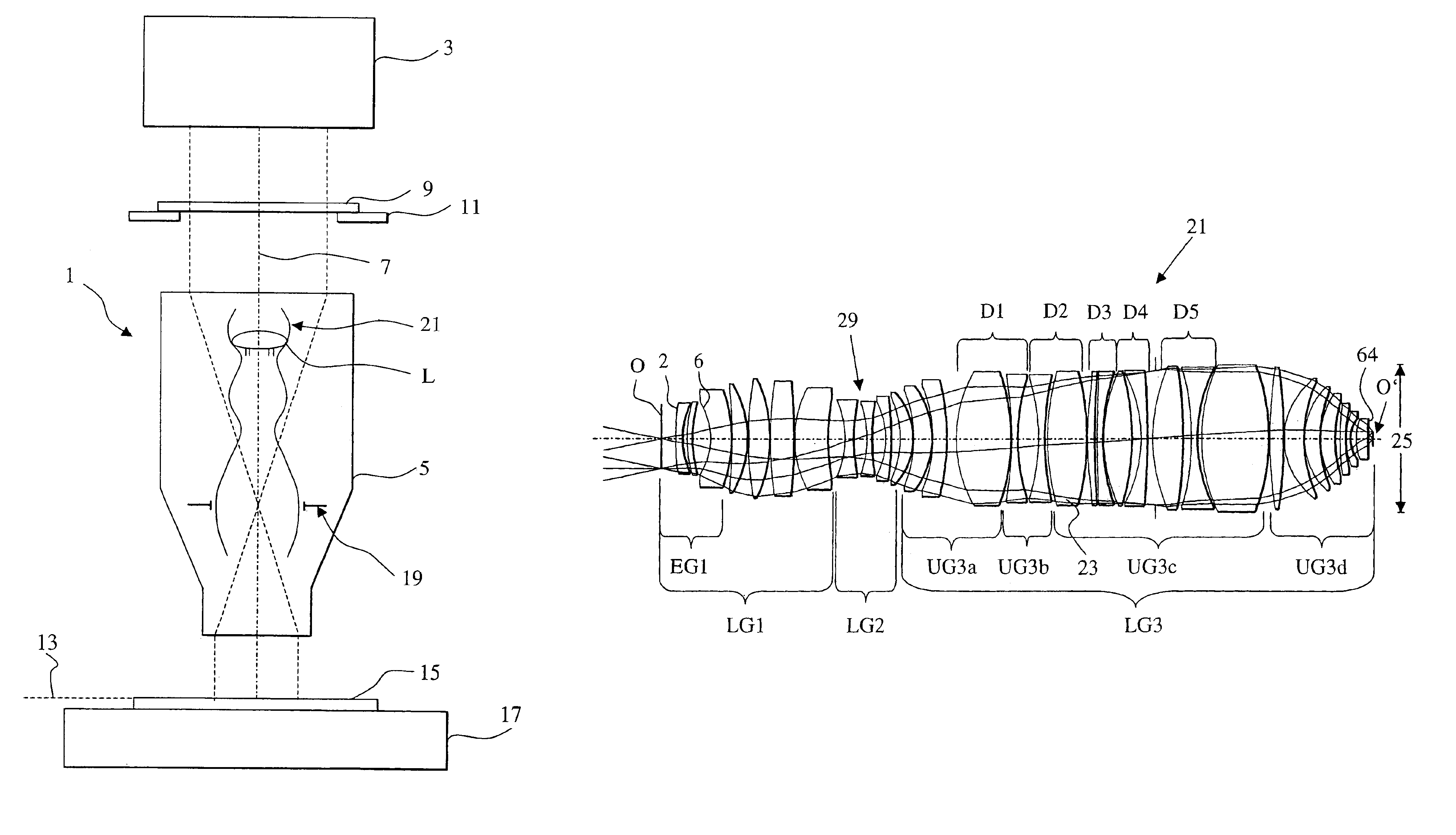
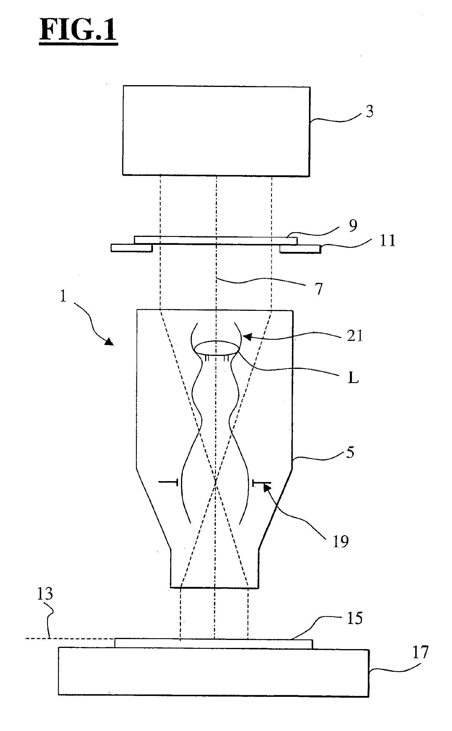
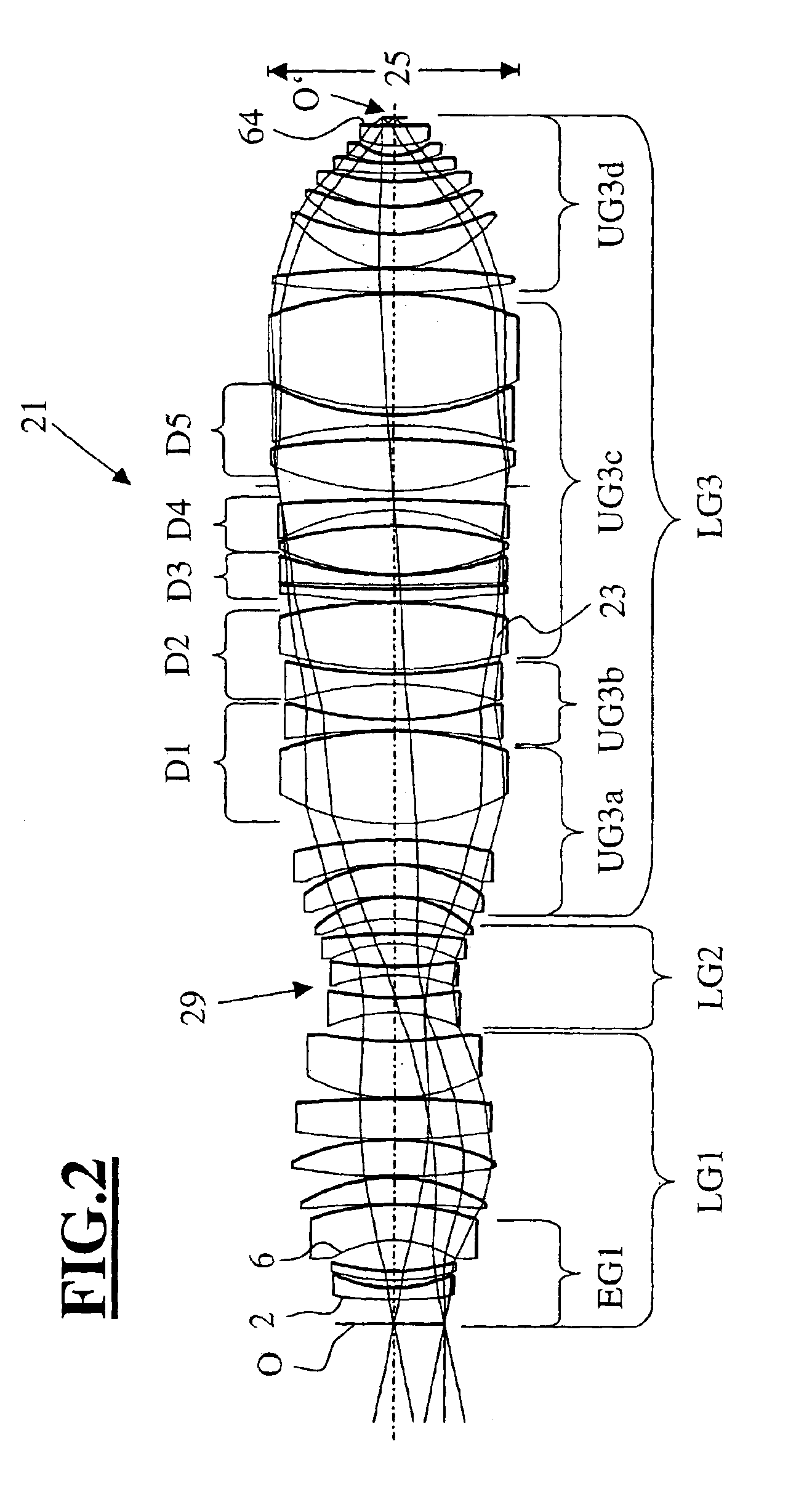
[0029]FIG. 1 serves to describe the principal layout of a projection system 1 for photographic exposures with a refractive projection objective 5. The projection system 1 has an illumination device 3 that is equipped with a means for narrowing the bandwidth. The projection objective 5 comprises a lens arrangement 21 with a system diaphragm 19, where the lens arrangement 21 defines an optical axis 7. A mask 9, which is held in the light path by means of a mask holder 11, is arranged between the illumination device 3 and the projection objective 5. Masks 9 of the kind used in microlithography carry a structure with detail dimensions in the micrometer to nanometer range, which is projected by means of the objective 5 onto an image plane 13 with a reduction in size by as much as a factor of 10, in particular a factor of 4. A substrate or wafer 15 is held in the image plane 13 by a substrate holder 17. The smallest detail dimensions of the structures that can be resolved in the image dep...


PUM

PropertyMeasurementUnit
wavelengthaaaaaaaaaa
refractive indexaaaaaaaaaa
wavelengthaaaaaaaaaa

Abstract

A refractive projection objective for use in microlithography with lenses made exclusively of one and the same material has an image-side numerical aperture larger than 0.7. A light bundle defined by the image-side numerical aperture and by the image field has within the objective a variable light-bundle diameter smaller than or equal to a maximum light-bundle diameter. In a length interval measured on the optical axis from the system diaphragm towards the object field and at least equaling the maximum light-bundle diameter, the variable light-bundle diameter exceeds 85% of the maximum light-bundle diameter.

Description

CROSS-REFERENCE TO RELATED APPLICATION[0001]This application is a continuation of International Patent Application Serial No. PCT / EP 03 / 01651 filed Feb. 19, 2003, which claims priority of U.S. Provisional Application Ser. No. 60 / 360,845 filed Mar. 1, 2002 and which is hereby incorporated by reference in its entirety.BACKGROUND OF THE INVENTION[0002]The invention relates to a projection system for making photographic exposures with a refractive projection objective. More specifically, the invention relates to the refractive projection objective itself as well as to a method involving the use of the projection system with the refractive projection objective in the manufacture of components carrying a microstructure. All lenses of the projection objective consist of the same material, and the numerical aperture of the projection objective on the image side is larger than 0.7.[0003]The German patent application DE 198 18 444 A1 discloses refractive projection objectives that are designe...

Claims


Application Information

Patent Timeline
Patent Type & Authority Patents(United States)
IPC IPC(8): G03F7/20G02B13/14
CPCG02B13/143G03F7/70975G03F7/70958G03F7/70241
Inventor SCHUSTER, KARL-HEINZ
Owner CARL ZEISS SMT GMBH
Why Eureka
Try Eureka