Optical packet header identifier, optical router incorporating the same therein, and optical routing method using the router

a technology of optical router and header identifier, which is applied in the direction of optical elements, multiplex communication, instruments, etc., can solve the problems of difficult delivery of ip packet to access paths, limited number of wavelengths to be allocated to individual addresses, and inapplicability of optical encoders, etc., to achieve the effect of simplifying configuration

Inactive Publication Date: 2005-05-10
LASERFRONT TECH
View PDF5 Cites 46 Cited by
  • Summary
  • Abstract
  • Description
  • Claims
  • Application Information

AI Technical Summary

Benefits of technology

[0037]Moreover, the optical packet header identifier makes it possible to construct an optical ADM and an optical router each incorporating the identifier therein and having a simplified configuration.

Problems solved by technology

However, this routing technique can be applied only to a high-speed / capacity portion of communication network because a wavelength resource, i. e., the number of wavelengths to be allocated to individual addresses is limited.
Currently, it is difficult to deliver an IP packet to an access path that needs a number of addresses while maintaining the packet in the form of light.
Furthermore, the optical encoder is not practical for use because it has no compatibility with the current optical fiber communication system in which data or address is transmitted / received by modulating the intensity of light.

Method used


Image

  • Optical packet header identifier, optical router incorporating the same therein, and optical routing method using the router
  • Optical packet header identifier, optical router incorporating the same therein, and optical routing method using the router
  • Optical packet header identifier, optical router incorporating the same therein, and optical routing method using the router

Examples


Embodiment Construction

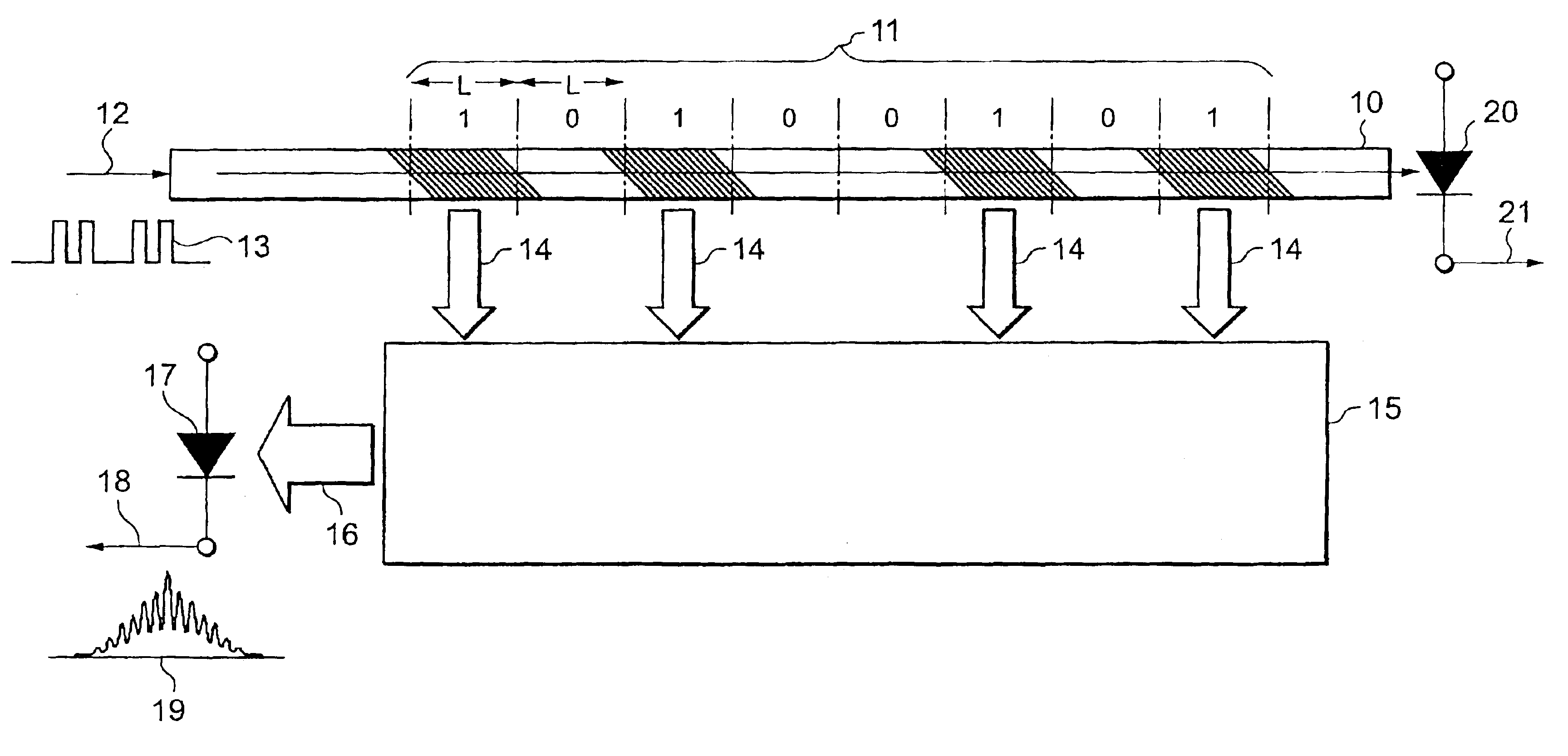
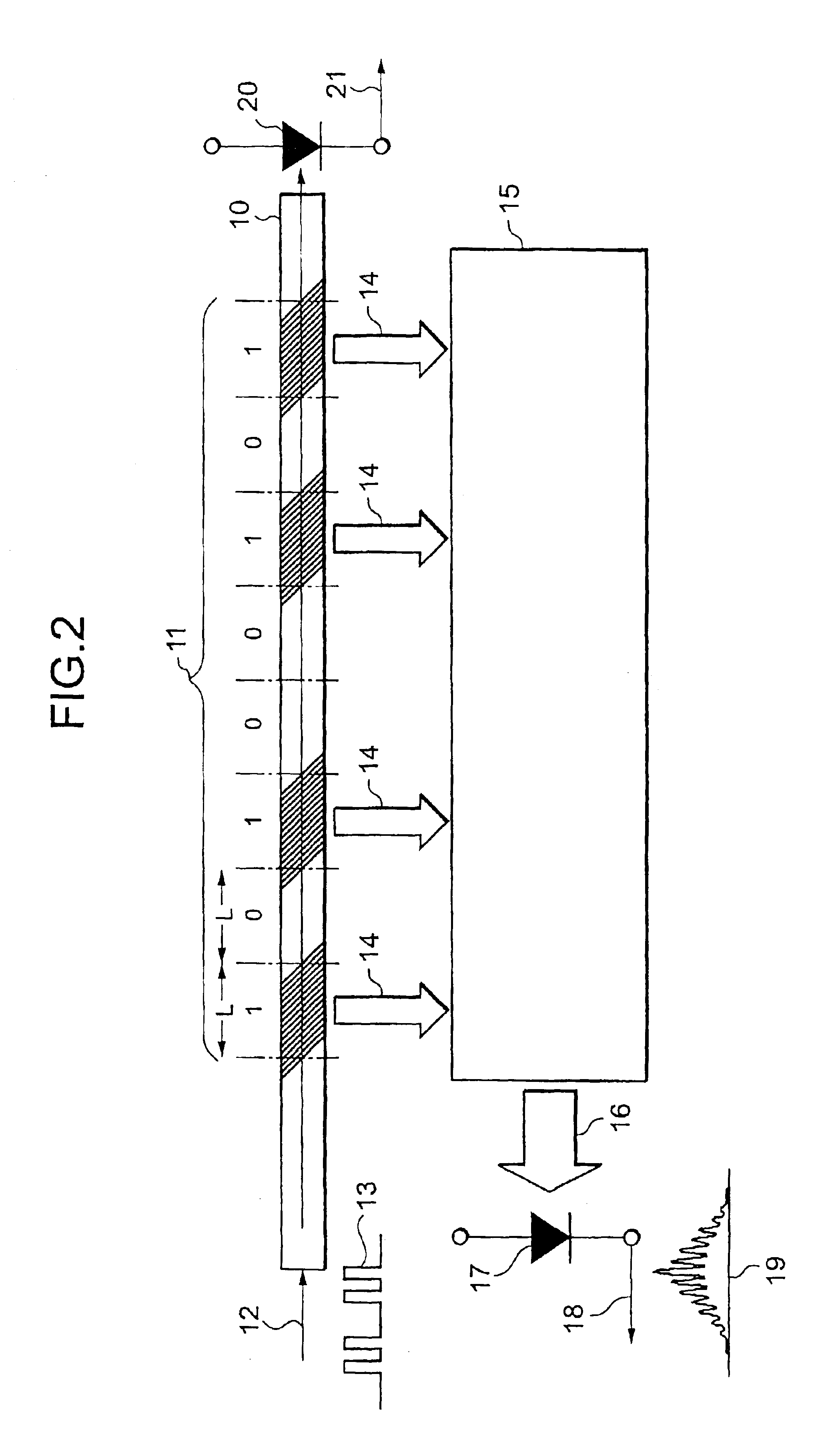
[0051]FIG. 2 is a diagram illustrating the general configuration of an optical packet header identifier according to the present invention. The optical packet header identifier comprises an optical waveguide 10, optical focusing means 15, and photo receivers 17 and 20, and tilted gratings 11 for diffracting an incident optical beam 12 to emit the beam as an emitted optical beam 14 to the outside of the waveguide is formed within the optical waveguide 10. The tilted gratings are not formed uniformly along the optical waveguide 10, but are constructed such that a plurality of sets of tilted gratings are arranged at intervals. The length of a portion containing a set of tilted gratings and the length of a portion containing no gratings, can be defined in increments of length “L.”“L” equals to the length that 1-bit in a digital optical signal 12 occupies within the waveguide 10. Arrangement of the plurality of sets of tilted gratings along an optical axis coincides with a previously giv...


PUM


Abstract

An optical packet header identifier having a simplified configuration and being superior in reliability, stability, and economical efficiency, an optical router incorporating the identifier therein, and a routing method using the optical router are provided. The optical packet header identifier includes an optical waveguide, optical focusing elements, and a photo receiver. Tilted gratings for diffracting an incident optical beam and emitting the beams as diffracted optical beams to the outside of the waveguide are formed within the optical waveguide. The tilted gratings are not formed uniformly in a longitudinal direction of a core of the optical waveguide, but are arranged at intervals. The length of a portion containing a set of gratings and the length of a portion containing no gratings can be defined in increments of length “L”. “L” equals to the spatial length which 1 bit in an optical signal occupies.

Description

BACKGROUND OF THE INVENTION[0001]1. Field of the Invention[0002]The present invention relates to an optical packet header identifier for verifying whether or not an optical address code added to an optical packet signal transmitted from outside coincides with an address code previously given to an optical packet receiver without photoelectric conversion while maintaining the added code in the form of light and for outputting a result of the coincidence of codes as an electrical signal output in the event the two codes coincide with one another, an optical router incorporating the identifier therein, and an optical routing method using the optical router.[0003]2. Description of the Related Prior Art[0004]Advent of the Internet community has been drastically increasing communication traffic. Therefore, there is a demand for realization of a network that is able to accept the increase in communication traffic, have a high-capacity, operate at higher rate, and have at lower communicatio...

Claims


Application Information

Patent Timeline
Patent Type & Authority Patents(United States)
IPC IPC(8): H04J14/02H04B10/152H04B10/158H04Q11/00G02B6/122G02B6/42H04B10/27H04B10/291H04B10/54
CPCH04B10/671H04B10/676H04J14/0212H04Q11/0005H04Q2011/0041H04Q11/0066H04J14/0227
Inventor OHTA, YOSHINORIOGURA, YUKIO
Owner LASERFRONT TECH
Why Eureka
Try Eureka