Irreversible circuit module including a directional coupler
a circuit module and directional coupler technology, applied in the direction of coupling devices, electrical devices, waveguides, etc., to achieve the effect of improving the insertion loss characteristics, reducing the number of circuit elements, and sufficient bonding strength
- Summary
- Abstract
- Description
- Claims
- Application Information
AI Technical Summary
Benefits of technology
Problems solved by technology
Method used
Image
Examples
example 1
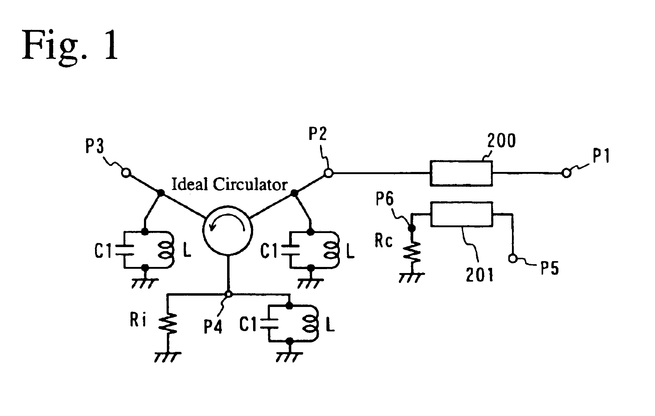
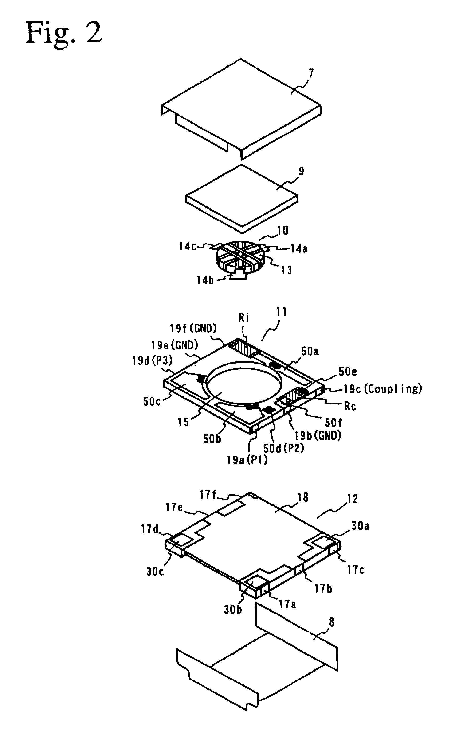
[0065]One example of the internal structure of the laminate 11 will be explained in a lamination order referring to FIG. 3. The laminate 11 is used for a non-reciprocal circuit module for W-CDMA (wideband CDMA, transmitted frequency TX: 1.92 GHz-1.98 GHz). For the simplicity of explanation, W-CDMA is taken as an example of a system for a wireless communications device, the same effects of the present invention can be obtained in the other systems.
[0066]First, the lowermost green sheet 112 is formed with a ground electrode 63 substantially on an entire rear surface, and then with electrodes 80a-80c, which are connected to connection electrodes 30a-30c formed on a resin base 12. After green sheets 111, 110 on which electrode patterns are not printed are laminated on the green sheet 112, a green sheet 109 provided with a line electrode 73 for constituting a first transmission line is laminated thereon. Laminated thereon are a green sheet 108 formed with a through-hole electrode (shown ...
example 2
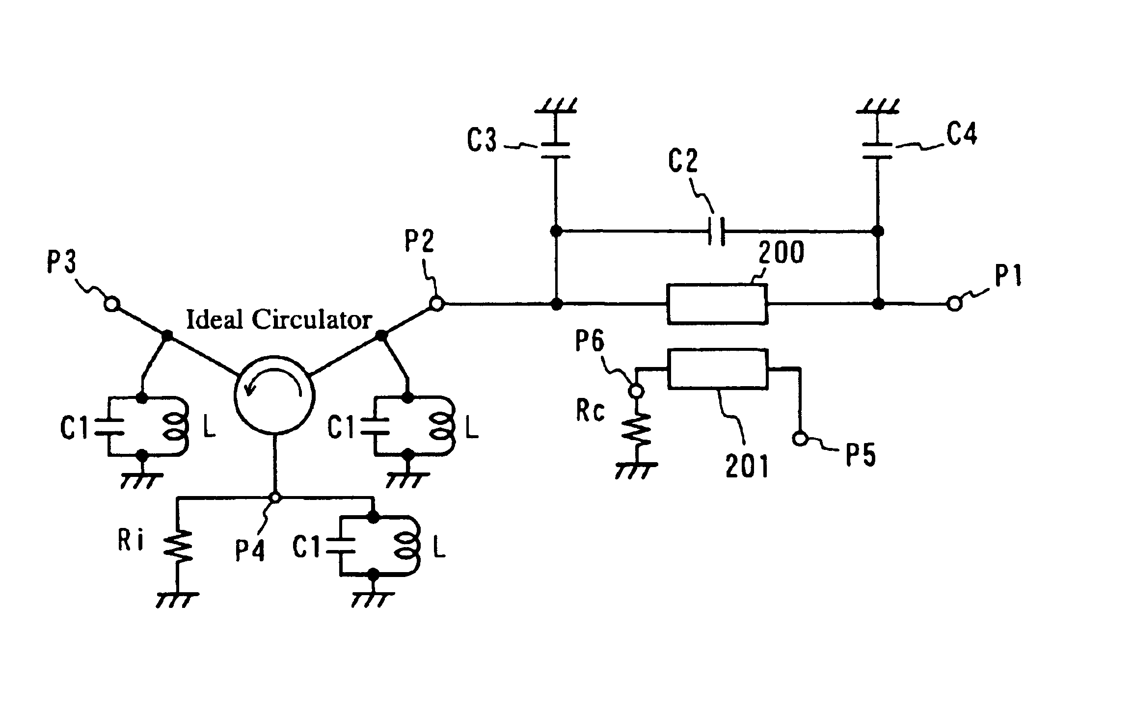
[0077]FIG. 5 shows an equivalent circuit of the non-reciprocal circuit module according to another embodiment of the present invention. This non-reciprocal circuit module is provided with the function of a directional coupler as well as the function of a low-pass filter.
[0078]Because the non-reciprocal circuit module of this example has the same portions as those of Example 1, only different portions are explained here. The differences from Example 1 are; (1) the first and second electrostatic capacitors C3, C4 are connected between both ends of the first transmission line and the ground to constitute a low-pass filter by the first transmission line and the first and second electrostatic capacitors C3, C4, and (2) the third electrostatic capacitor C2 is connected in parallel to the first transmission line to have sharp attenuation.
[0079]FIG. 6 is an exploded perspective view showing the laminate 11 of this example. The differences from Example 1 are that an electrode 300 for an elec...
example 3
[0082]Though Examples 1, 2 are directed to the non-reciprocal circuit module for W-CDMA, this example is directed to a non-reciprocal circuit module for D-AMPS (digital-advanced mobile phone service, transmitted frequency TX: 824 MHz-849 MHz).
[0083]In general, as a frequency handled decreases, any of the inductance, load capacitance and line length of a directional coupler should be increased, resulting in difficulty in the miniaturization. Thus, part of a circular pore 16 of the laminate 11 in this example is buried as shown in FIG. 9. This provides advantages of increasing the area of an electrode pattern on the green sheet and the capacitance of the load capacitor C1, thereby stabilizing the ground. Therefore, the magnetic body 13 has a deformed circular shape of 2.5 mm in diameter partially cut by 0.75 mm from a periphery in this Example.
[0084]The internal structure of the laminate 11 is explained in a lamination order referring to FIG. 10. The lowermost green sheet 112 is provi...
PUM
 Abstract
Description
Claims
Application Information
 - R&D
- Intellectual Property
- Life Sciences
- Materials
- Tech Scout
- Unparalleled Data Quality
- Higher Quality Content
- 60% Fewer Hallucinations
Browse by: Latest US Patents, China's latest patents, Technical Efficacy Thesaurus, Application Domain, Technology Topic, Popular Technical Reports.
© 2025 PatSnap. All rights reserved.Legal|Privacy policy|Modern Slavery Act Transparency Statement|Sitemap|About US| Contact US: help@patsnap.com


