Illumination optical system and laser processor having the same

a laser processor and optical system technology, applied in the field of illumination optical systems, can solve the problems of difficult manufacturing of cylindrical lenses, poor shaping precision of spherical lenses, and high manufacturing cost, and achieve the effects of superior image formation capability, excellent illumination uniformity, and large aspect ratio

Inactive Publication Date: 2005-05-17
IHI CORP
View PDF15 Cites 33 Cited by
  • Summary
  • Abstract
  • Description
  • Claims
  • Application Information

AI Technical Summary

Benefits of technology

[0045]As described above, this invention makes it possible to provide an illumination optical system which has superior image formation capabilities, and can radiate a linear beam with excellent illumination uniformity and a narrow line width having a large aspect ratio

Problems solved by technology

However, the following problems arise when using a large number of cylindrical lenses, as described in the above publication.
Making a cylindrical lens is not as easy as a normal spherical-faced lens, and the manufacturing cost is higher.
Furthermore, the shaping precision is greatly inferior to that of the normal spherical-faced lens.
Considering the manufacture of an actual apparatus, there is a possibility that an optical system comprising a great number of cylindrical lenses will increase the manufacturing cost and fail to satisfy demands for high work precision.
As a result, when the beam is radiated onto a sample, it is difficult to heat the sample to the temperature required for anneal processing.
However, the excimer laser is expensive, and the apparatus itself is large.
In view of the demand for this type of image formation capability, the specifications of the optical system disclosed in Japanese Patent Laid-Open No. 10-244392, mentioned above, are inadequate.
The aberration of this light beam cannot easily be corrected by an optical system which simply combines power in intersecting directions.
Therefore, this design method is not desirable when attempting to correct the aberration of the optical system to a high level.
Generally, optical designers are not familiar with the characteristic aberration of cylindrical lenses described above.
It is extremely difficult to correct the characteristic aberration of the cylindrical lens with only a combination of cylindrical lenses with intersecting powers.
Even if the aberration were to be corrected, the large number of cylindrical lenses required would be enormous.
As described above, when making a linear beam with a narrow width, an optical system which uses a large number of intersecting cylindrical lenses is not desirable from an optical design point of view.
However, this structure is not desirable for working a linear beam with a narrow width, for the following reasons.
However, when the linear beam has poor illumination uniformity, energy decreases at the peripheral portions of the beam width.
This is equivalent to scanning a linear beam with a narrow width, and makes it impossible to increase the scanning speed.
It is extremely difficult to make a linear beam with a narrow width after aberration has been corrected to a high degree, while maintaining highly uniform illumination in the short (width) direction of the linear beam.
For this point of view, the optical system disclosed in Japanese Unexamined Patent Application, First Publication No. 10-244392 cannot be regarded as adequate.
Furthermore, in an optical system which emits laser light over an extremely large scanning range, it is very difficult to increase the number of apertures (NA) in the optical system on the emission side.
This causes diffraction, so that optical considerations alone are not sufficient to analyze the uniform illumination of the linear beam.
In other words, the precise reconnection of the linear image becomes more difficult as the required line width becomes narrower.

Method used


Image

  • Illumination optical system and laser processor having the same
  • Illumination optical system and laser processor having the same
  • Illumination optical system and laser processor having the same

Examples


first embodiment

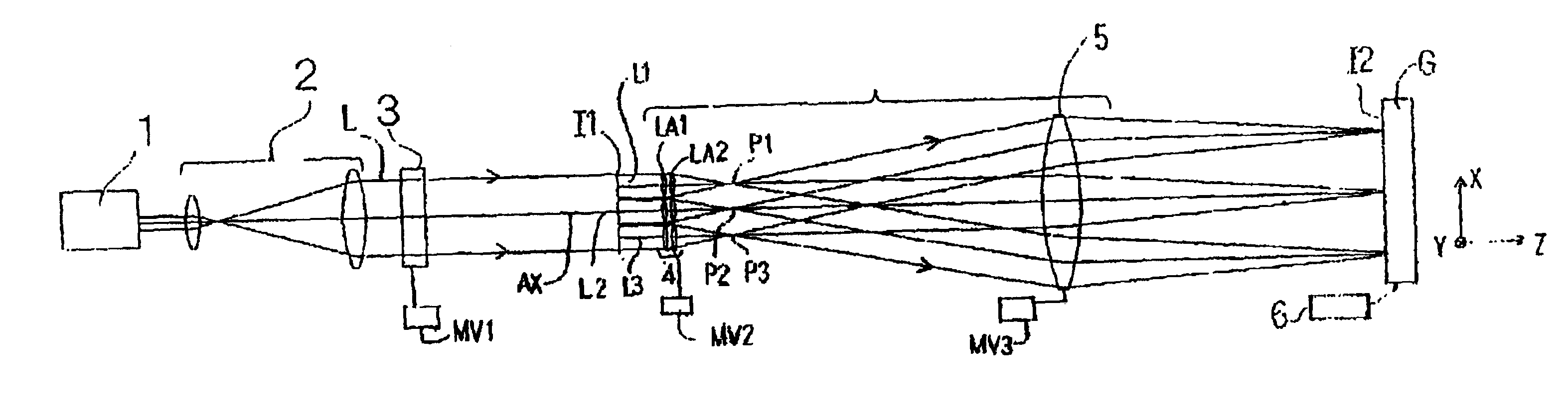
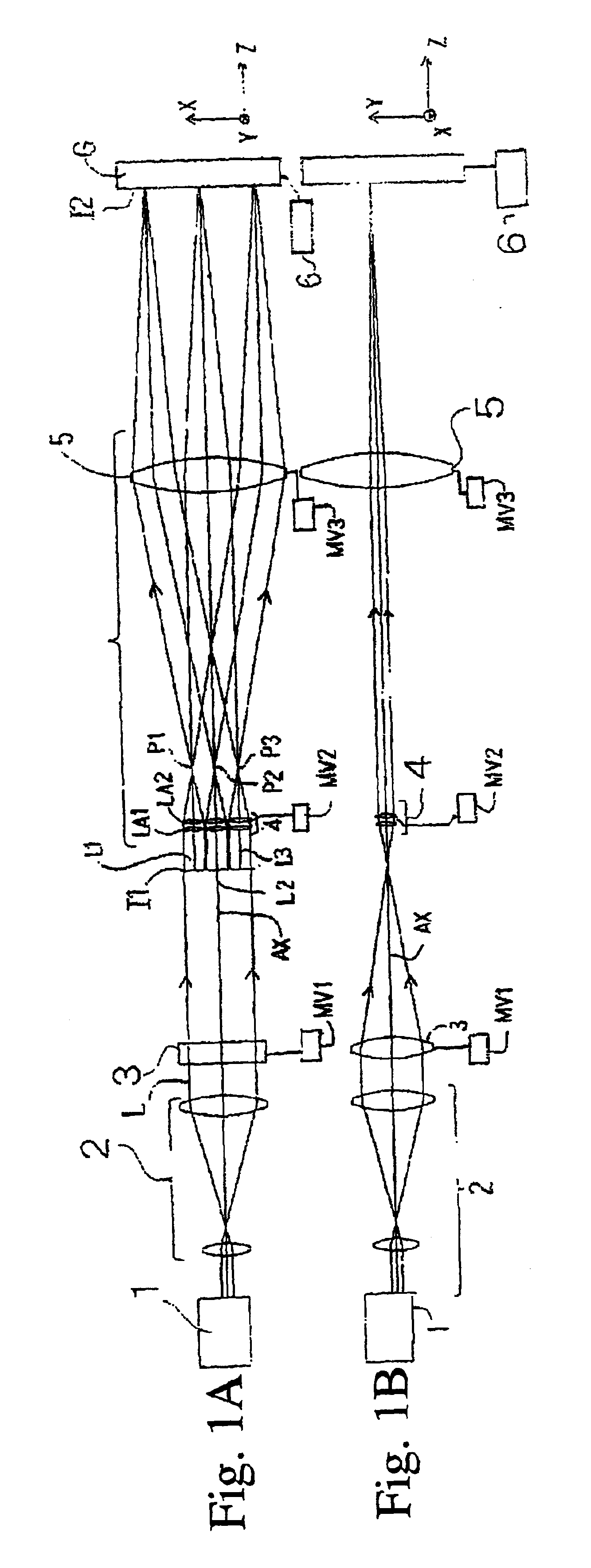
[0055]FIGS. 1A and 1B show a schematic constitution of a laser processing apparatus according to a first embodiment. A fixed laser 1 emits a laser beam which is substantially circular in cross-section, and an afocal beam expander 2 expands the ray bundle diameter of the beam, converting it to collimate light with a large diameter. The collimate light L is radiated to a cylindrical lens 3. The cylindrical lens 3 has no refractive power in the x direction (non-power face) and has positive refractive power in the y direction, which is substantially perpendicular to the x direction. Therefore, the light passes the cylindrical lens 3 and is focused on an intermediate image-forming face I1 into a line, the long side of this line being parallel to the x direction.

[0056]Here, the intensity distribution of the laser beam which is substantially circular in cross-section, emitted by the light source 1, has Gauss distribution. Since the circular beam is converted to a linear image by the cylind...

second embodiment

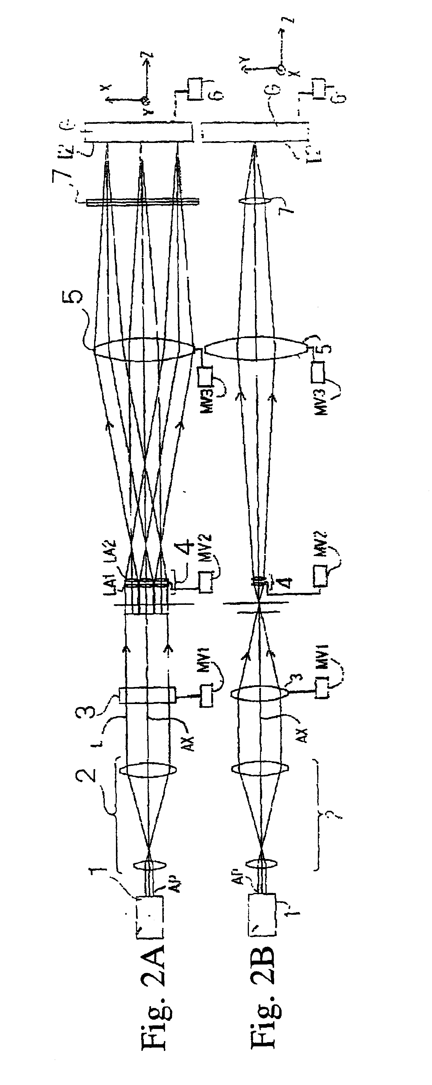
[0076]FIGS. 2A and 2B show the schematic structure of a laser processor according to a second embodiment. A cylindrical lens 7 has positive (convex) power, and is newly appended between the condenser lens 5 and the illuminated face I2. Since the constitution is otherwise identical to that of the first embodiment, the same reference codes are used for the same parts and the explanation of these parts is not repeated.

[0077]In the second embodiment, the linear image made by the cylindrical lens 3 is reformed on the illuminated face I2. That is, the linear image made by the cylindrical lens 3 functions jointly with the illuminated face I2. Consequently, in comparison with the first embodiment, the position of the linear image made by the cylindrical lens 3 (intermediate image-forming face) is defocused toward the lens array 4.

[0078]The cylindrical lens 7 enables the focal length in the width direction of the linear image to be changed more freely when setting the lenses.

[0079]With regar...

third embodiment

[0084]FIGS. 4A and 4B show a schematic constitution of the laser processor according to the third embodiment. A YAG laser 101 emits a laser beam which is substantially circular in cross-section, and a beam expander 102 converts the beam to collimate light which is elliptical in cross-section. At this time, the long axis of the ellipse is in the x direction, and its short axis is in the y direction. The structure of the beam expander 102 and the method of converting the cross-sectional shape of the beam will be explained later.

[0085]Subsequently, the beam enters a trapezoid prism 103 and is split into three beams radiating in different directions. The split direction matches the long direction (x direction) of the elliptical beam. The three split beams are radiated to a cylindrical lens 104. The cylindrical lens 104 has positive refractive power in the y direction, which intersects the x direction at a right angle. The shape and position of the trapezoid prism 103 are determined so t...


PUM

PropertyMeasurementUnit
aberration slope angleaaaaaaaaaa
refractive poweraaaaaaaaaa
optical axesaaaaaaaaaa

Abstract

An illumination optical system has superior image formation capabilities, and can radiate a linear beam with excellent illumination uniformity and a narrow line width having a large aspect ratio; the illumination optical system comprises an afocal beam expander system which expands an beam illuminated from a laser light source; a linear beam-forming lens system having at least refractive power in a second direction which is substantially at a right angle to at least a first direction, the linear beam-forming lens system converting the beam, illuminated from said beam expander system, to a linear beam having its long side in said first direction; a lens array section having a plurality of element lenses, arranged along said first direction; and a condenser optical system which illuminates a processed face by reconnecting images of said linear beam from each of said element lenses thereon.

Description

BACKGROUND OF THE INVENTION[0001]1. Field of the Invention[0002]The present invention relates to an illumination optical system which is suitable for anneal processing of a glass substrate and the like, and a laser processor incorporating the optical system.[0003]2. Description of the Related Art[0004]One conventional crystallizing technique is performed by radiating laser light onto an amorphous silicon film. There is another technique of radiating laser light in order to repair the crystal properties of the silicon film, which is damaged by the injection of impurity ions, and to revitalize injected impurity ions. This is called a laser anneal method.[0005]One characteristics of laser anneal processing is that there is almost no heat damage to the substrate. This characteristic of causing no heat damage to the substrate is useful when, for example, providing a semiconductor element on a substrate having low heat-resistance, such as glass.[0006]Recently, a glass substrate is prefera...

Claims


Application Information

Patent Timeline
Patent Type & Authority Patents(United States)
IPC IPC(8): G02B1/12G02B1/10G03F7/20
CPCG02B1/12G03F7/20
Inventor SUGIYAMA, YOSHIKAZUMASAKI, MIYUKIYAGI, TAKEHITO
Owner IHI CORP
Why Eureka
Try Eureka