Combustion engine, gas turbine, and polishing layer

a combustion engine and gas turbine technology, applied in the direction of machines/engines, climate sustainability, waterborne vessels, etc., can solve the problem of high grinding performance for a long time period

Inactive Publication Date: 2005-05-24
MITSUBISHI HEAVY IND LTD
View PDF20 Cites 16 Cited by
  • Summary
  • Abstract
  • Description
  • Claims
  • Application Information

AI Technical Summary

Benefits of technology

[0017]Also, the above-described abrasive layer is well-suited to a gas turbine which has a tendency for the temperature of combustion gas to be high among the combustion engines. In particular, in a gas turbine

Problems solved by technology

Thereby, high grinding performance continue

Method used


Image

  • Combustion engine, gas turbine, and polishing layer
  • Combustion engine, gas turbine, and polishing layer
  • Combustion engine, gas turbine, and polishing layer

Examples


Embodiment Construction

[0025]A combustion engine, a gas turbine, and an abrasive layer in accordance with the present invention will now be described with reference to the accompanying drawings.

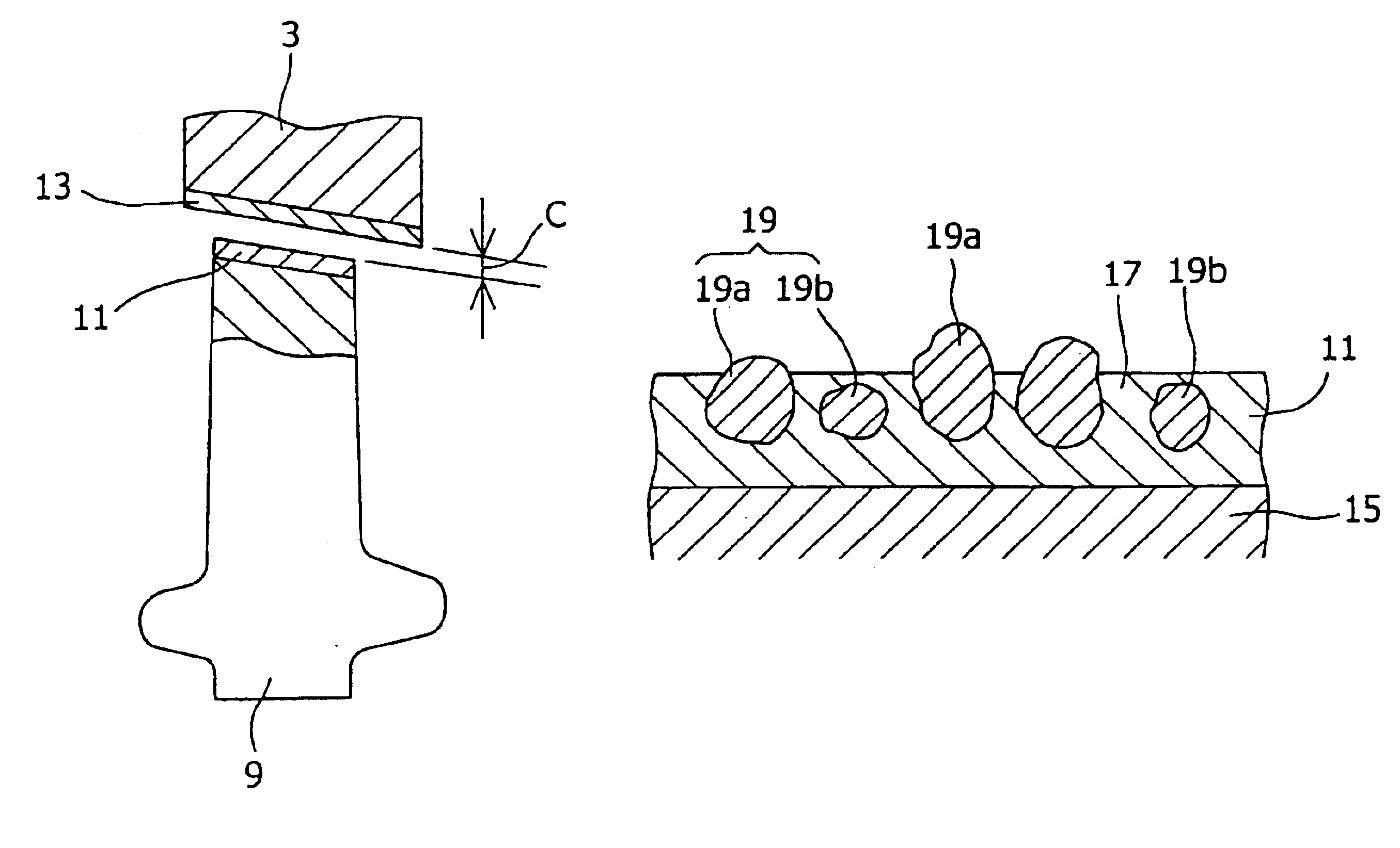
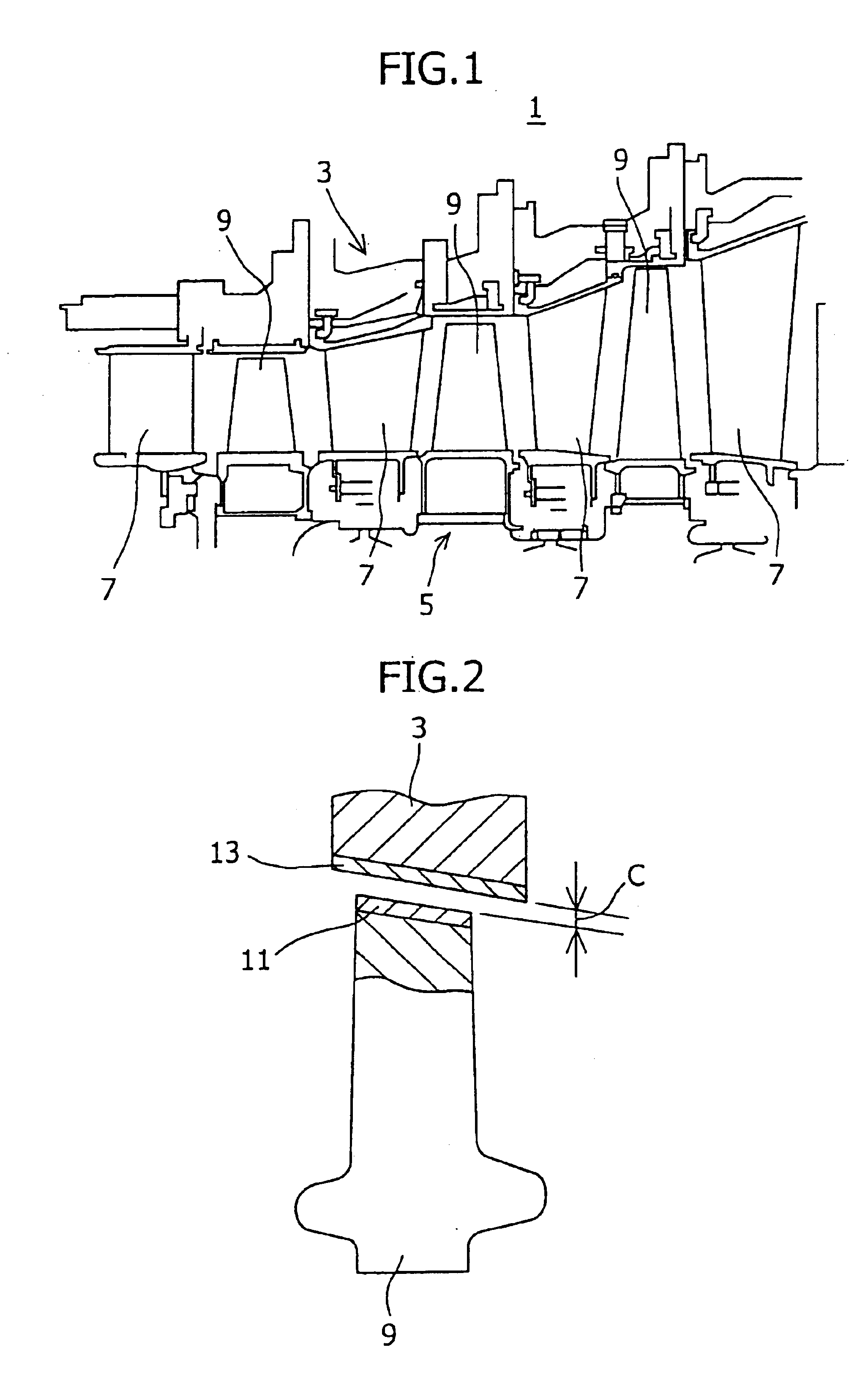
[0026]FIG. 1 is a partially sectional view of a turbine portion 1 of a gas turbine in accordance with one embodiment of the present invention, in which the turbine portion 1 is cut in the axial direction.

[0027]This turbine portion 1 includes a shroud 3, a rotor 5, a plurality of stator blades 7, and a plurality of rotor blades 9 planted in the rotor 5. The stator blades 7 and the rotor blades 9 are arranged alternately in the axial direction (right-and-left direction in FIG. 1). Although not shown in the figure, the gas turbine is provided with a compressor and a combustor on the upstream side (that is, the left-hand side) of the turbine portion 1.

[0028]Air is compressed in the compressor, and the compressed air is sent into the combustor. In the combustor, a fuel is mixed with the compressed air, and the fuel-air ...


PUM

PropertyMeasurementUnit
Temperatureaaaaaaaaaa
Fractionaaaaaaaaaa
Fractionaaaaaaaaaa

Abstract

The present invention provides a gas turbine in which a proper clearance is kept between a rotor blade and a shroud for a long period of time from the operation start, so that damage to the rotor blade is less liable to occur. In a turbine portion of the gas turbine in accordance with the present invention, the rotor blade and the shroud face each other. At the tip end of the rotor blade is formed an abrasive layer, and on the inner peripheral surface of the shroud is formed a heat insulating layer. The abrasive layer is formed of a matrix and many abrasive particles dispersed in the matrix. The abrasive particles include protruding particles protruding from the matrix and embedded particles embedded in the matrix. In initial sliding of the rotor blade and the shroud at the early stage of operation, the inner peripheral surface of the shroud is ground by the protruding particles. After the protruding particles have disappeared, the inner peripheral surface of the shroud is ground by the embedded particles.

Description

TECHNICAL FIELD[0001]The present invention relates to a combustion engine and a gas turbine having an abrasive layer formed on the surface of either one of a movable portion and a non-movable portion facing each other, such as a shroud formed at the tip end of a turbine rotor blade or around a rotor blade provided in a combustion engine such as a jet engine and a gas turbine, and an abrasive layer.BACKGROUND ART[0002]Between the tip end of a rotor blade of a gas turbine and a shroud facing the tip end of the rotor blade, a clearance of a predetermined size is provided to prevent the tip end of the rotor blade from coming into contact with the shroud during the operation. If the clearance is too large, combustion gas leaks from the pressure surface side to the negative pressure surface side of the rotor blade, so that a pressure loss increases, and thus the operation efficiency of gas turbine decreases. In order to prevent this phenomenon and to thereby improve the performance of gas...

Claims


Application Information

Patent Timeline
IPC IPC(8): C25D15/02C25D15/00F01D11/08F01D5/14F01D5/20F01D11/12F02C7/28
CPCC25D15/02F01D5/20F01D11/122F01D11/12F05D2250/621Y02T50/67Y02T50/60
Inventor OHARA, MINORUMEGA, MASAHIKO
Owner MITSUBISHI HEAVY IND LTD
Why Eureka
Try Eureka