Personal electro-kinetic air transporter-conditioner

Inactive Publication Date: 2005-05-24
THE SHARPER IMAGE
View PDF243 Cites 34 Cited by
  • Summary
  • Abstract
  • Description
  • Claims
  • Application Information

AI Technical Summary

Benefits of technology

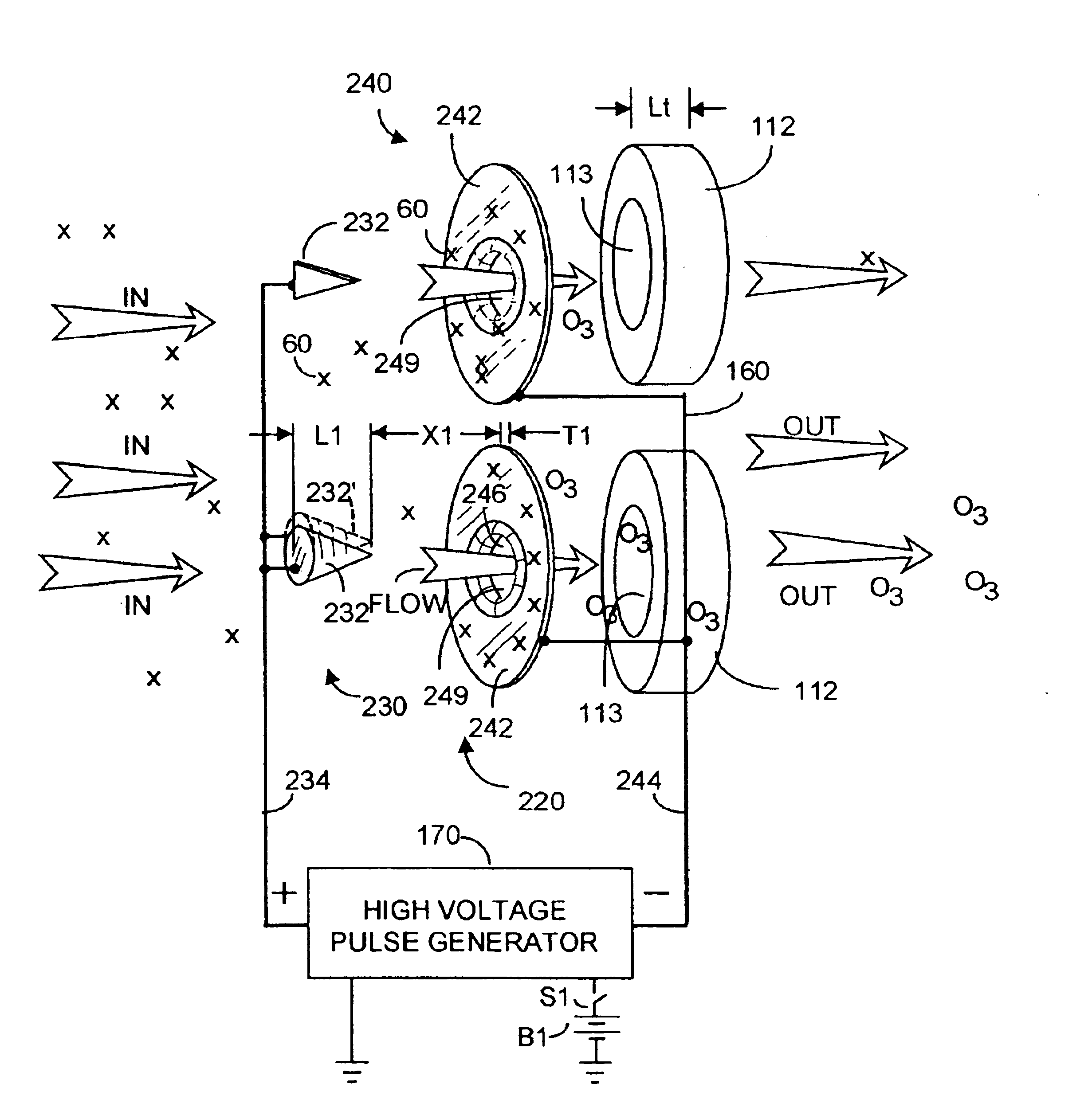
[0016]The high voltage pulses create an electric field between the first and second electrode arrays in each electrode assembly. This field produces an electro-kinetic airflow going from the first array toward the second array, the airflow being rich in preferably a net surplus of negative ions and in ozone. Ambient air including dust particles and other undesired components (germs, perhaps) enter the housing through the input vent, and ionized clean air (with ozone) exits through openings on the downstream side of the housing. When the moisture-containing member is wet, the

Problems solved by technology

Unfortunately, such fans produce substantial noise, and can present a hazard to children who may be tempted to poke a finger or a pencil into the moving fan blade.
Unfortunately, the resistance to air flow presented by the filter element may require doubling the electric motor size to maintain a desired level of airflow.
Further, HEPA-compliant filter elements are expensive, and can represent a substantial portion of the sale price of a HEPA-compliant filter-fan unit.
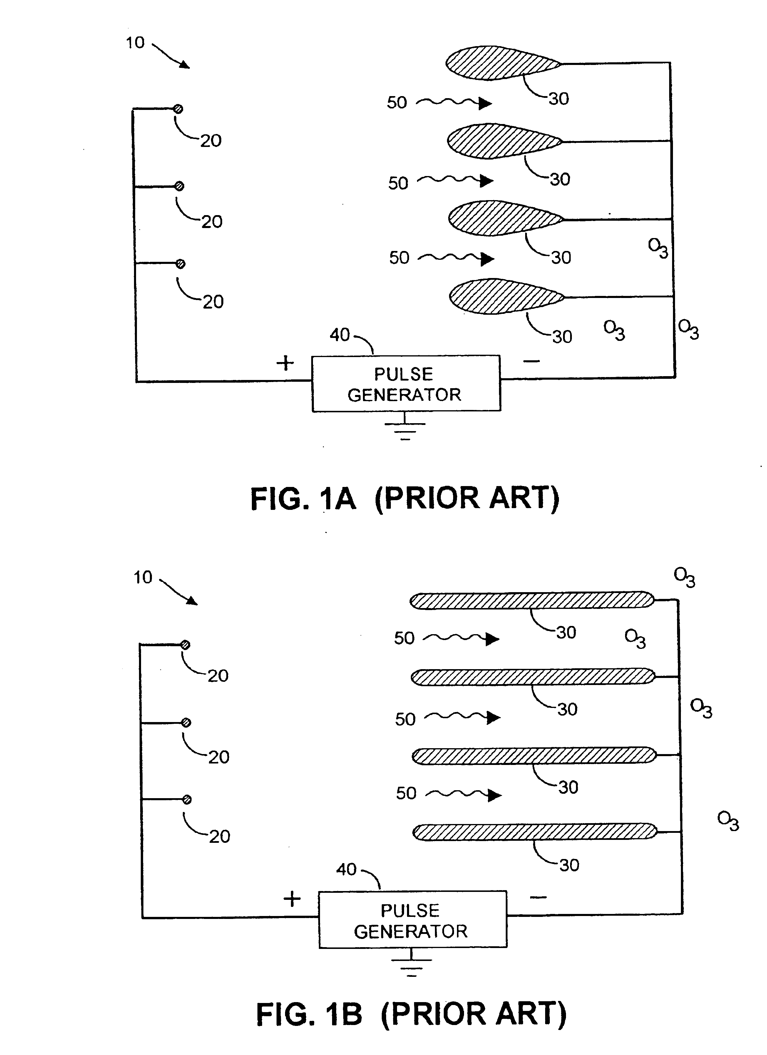
Further, the high voltage field present between the electrode arrays can release ozone into the ambient environment, which appears to destroy or at least alter whatever is entrained in the airflow, including for example, bacteria.
Lee does not disclose how the teardr

Method used


Image

  • Personal electro-kinetic air transporter-conditioner
  • Personal electro-kinetic air transporter-conditioner
  • Personal electro-kinetic air transporter-conditioner

Examples


Embodiment Construction

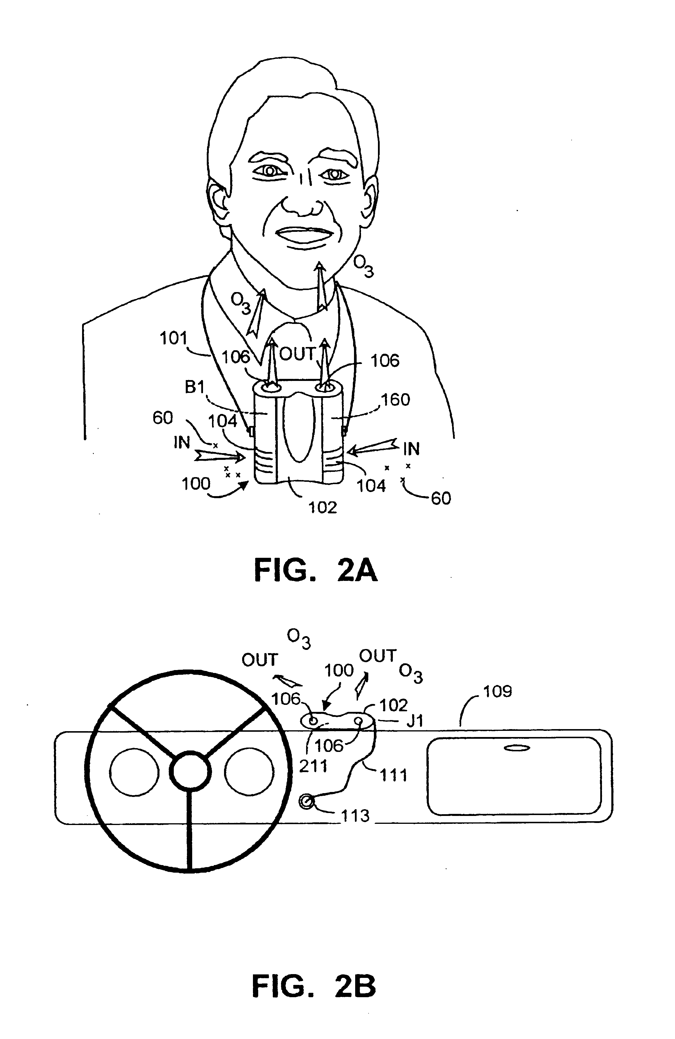
[0042]FIG. 2A depicts a preferred embodiment of an electro-kinetic air transporter-conditioner system 100 suspended by a flexible cord 101 from the neck of a user. System 100 is formed within a housing 102 that preferably is a lightweight easily formed material, ABS plastic for example. Housing 102 includes ambient air intake vents 104 and at least one and preferably two output or exhaust vents 106. Ambient air enters vents 104 and exits vents 106, preferably with a higher moisture content, with at least some particulate matter in the ambient air removed (e.g., dust), and with safe amounts of ozone (O3). Housing 102 contains an ion generating unit 160, powered from a battery source B1, also disposed within the housing. Ion generating unit 160 is self-contained in that other than ambient air, nothing is required from beyond the transporter housing for operation of the present invention.

[0043]FIG. 2B depicts system 100 mounted on or to the interior of a motor vehicle, for example, mou...


PUM

PropertyMeasurementUnit
Fractionaaaaaaaaaa
Fractionaaaaaaaaaa
Timeaaaaaaaaaa

Abstract

A personal electro-kinetic electro-static air conditioner includes a self-contained ion generator that provides electro-kinetically moved air with ions and safe amounts of ozone, and includes a water retaining element to increase humidity of the output air flow. The ion generator includes a high voltage pulse generator whose output pulses are coupled between first and second electrode arrays. Preferably the first electrode array includes first and second pointed electrodes, and the second electrode array includes annular-like electrodes having a central opening coaxial with the associated pointed electrode. The surface of the annular-like electrodes is smooth and continuous through the opening and into a collar region through which the air flows. A water retaining member is disposed surrounding the output airflow to increase humidity of the output air, which is substantially cleansed of particulate matter, and contains safe amounts of ozone.

Description

RELATION TO CO-PENDING APPLICATION[0001]This application is a continuation of U.S. patent application Ser. No. 09 / 669,253, filed Sep. 25, 2000 entitled PERSONAL ELECTRO-KINETIC AIR TRANSPORTER-CONDITIONER, now U.S. Pat. No. 6,632,407 which is a continuation-in-part of U.S. patent application Ser. No. 09 / 186,471, filed Nov. 5, 1998 entitled ELECTRO-KINETIC AIR TRANSPORTER-CONDITIONER, now U.S. Pat. No. 6,176,977.FIELD OF THE INVENTION[0002]This invention relates to electro-kinetic conversion of electrical energy into fluid flow of an ionizable dielectric medium in which an electro-kinetically produced flow of air is created, the air containing safe amounts of ozone and from which air particulate matter has been substantially removed, and more particularly to portable such units adapted for use in a confined area in which some degree of humidity control is desired.BACKGROUND OF THE INVENTION[0003]The use of an electric motor to rotate a fan blade to create an air flow has long been kn...

Claims


Application Information

Patent Timeline
IPC IPC(8): B01D53/32B03C3/04B03C3/12C01B13/11H01T23/00A61L9/015A61L9/22B01J19/08B03C3/02B03C3/40B03C3/41B03C3/45B03C3/47B03C3/74
CPCB01D53/32H01T23/00B03C3/08B03C3/12B03C3/32B03C3/68B03C3/743C01B13/11C01B13/115B01D53/323B01D2251/104B03C2201/08B03C2201/14C01B2201/12C01B2201/20C01B2201/22C01B2201/62F24F2003/1682F24F2003/1685F24F8/30F24F8/40
Inventor LAU, SHEK FAITAYLOR, CHARLES E.
Owner THE SHARPER IMAGE
Why Eureka
Try Eureka