Control of oxygen precipitate formation in high resistivity CZ silicon

a technology of oxygen precipitate and silicon, which is applied in the field of silicon wafers and semiconductor material substrates, can solve the problems of molten silicon contamination with various impurities, precipitates can be harmful or beneficial, and device operation, and achieve high resistivity surface layers, high resistivity, and high oxygen density

Inactive Publication Date: 2005-05-24
GLOBALWAFERS CO LTD
View PDF54 Cites 30 Cited by
  • Summary
  • Abstract
  • Description
  • Claims
  • Application Information

AI Technical Summary

Benefits of technology

[0009]Among the features of the present invention, therefore, is the provision of a single crystal silicon wafer, and a process for the preparation thereof, which has at least a high resistivity surface layer; the provision of such as wafer which, upon being subjected to an oxygen precipitation heat-treatment, has a high resistivity denu

Problems solved by technology

Molten silicon is contaminated with various impurities, among which is mainly oxygen, during the time it is contained in a quartz crucible.
Depending upon their location in the wafer and their relative size, the precipitates can be harmful or beneficial.
Large oxygen precipitates located in the active device region of the wafer can impair the operation of the device but when located in the bulk of the wafer, however, are capable of trapping undesired metal impurities that may come into contact with the wafer during, for example, device fabrication processes.
In addition, the relatively high levels of Oi present in CZ silicon, typically in the range of 10-15 parts per million atomic or “ppma,” can be problematic.
(temperatures commonly employ

Method used


Image

  • Control of oxygen precipitate formation in high resistivity CZ silicon
  • Control of oxygen precipitate formation in high resistivity CZ silicon
  • Control of oxygen precipitate formation in high resistivity CZ silicon

Examples


example 1

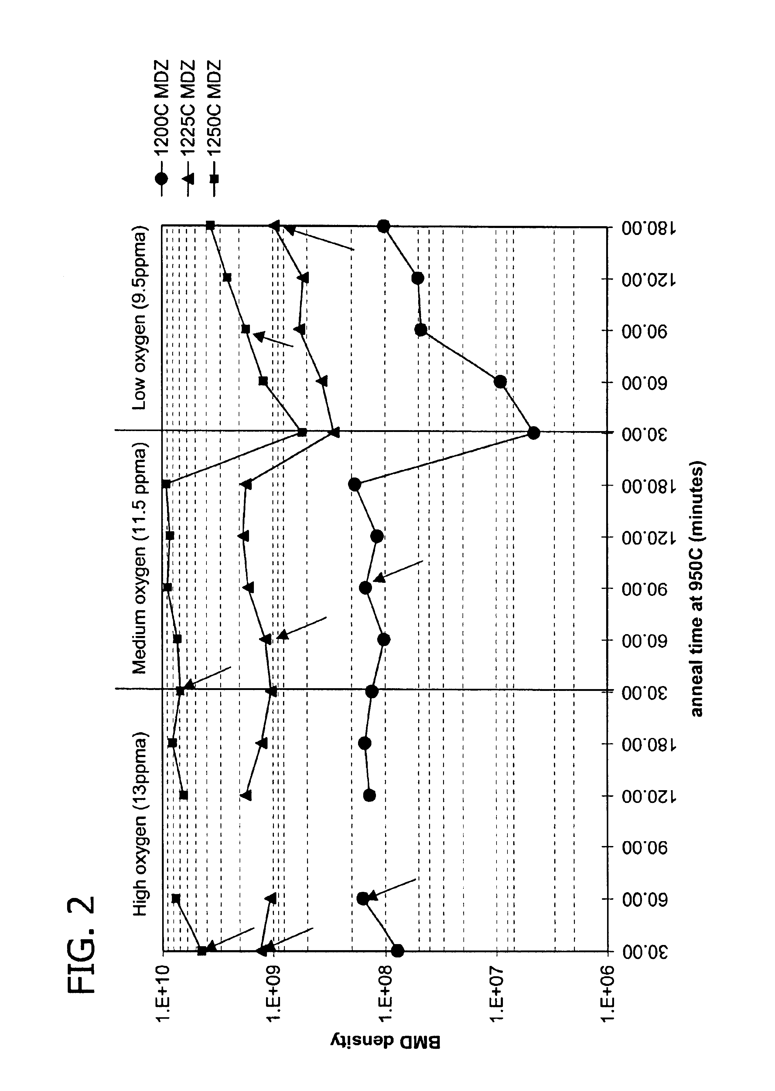
[0073]Example 1 and FIG. 2 demonstrate the gettering capability of ideal precipitating wafers over a range of oxygen concentration. In the first set of experiments, ideal precipitating wafers with an oxygen concentration of 13 ppma were produced at a step S1 heat treatment temperature of 1200° C., followed by oxygen bulk precipitate growth at 950° C. over a range of 30 minutes to 180 minutes. The evaluations were repeated for 1225° C. and 1250° C. step S1 heat treatment temperatures. In a second and third set of experiments, the first set of experiments were repeated for ideal precipitating wafers with oxygen concentrations of 11.5 ppma and 9.5 ppma respectively. Gettering capability was measured by contaminating the wafer back surface with nickel. The arrows in FIG. 2 indicate the onset of complete gettering. The data show that bulk precipitate density above the threshold for effective gettering may be obtained for ideal precipitating wafers over a range of oxygen concentration, an...

example 2

[0074]Four wafers were cut from two sections of a high resistivity CZ crystal. Three wafers were given ideal precipitating wafer heat-treatments at 1235° C., 1250° C. and 1275° C., respectively. The fourth wafer was a control that was not given an ideal precipitating wafer heat-treatment. Each wafer was then quartered and given the following secondary anneals:

[0075]

Wafer GG, Quarter 1 (GGQ1):4 hours at 800° C. followed by 16hours at 1000° C.;Wafer GG, Quarter 2 (GGQ2):8 hours at 800° C. followed by 16hours at 1000° C.;Wafer GG, Quarter 3 (GGQ3):ramp from 800° C. to 1000° C. at1° C. / min followed by 1 hour at1000° C.; andWafer GG, Quarter 4 (GGQ4):ramp from 800° C. to 1000° C. at2° C. / min followed by 1 hour at1000° C.

[0076]Following the secondary anneals, the BMD density was measured by OPP (Optical Precipitate Profiler). The OPP method is an applied method of Normalski type differential interference microscope. In the method, laser beam from light source is separated to two orthogona...

example 3

[0079]The radial initial and final oxygen concentration (Oi) of the annealed GG wafers from Example 2, a second set of wafers (GA) prepared as in example 2, and corresponding untreated GG and GA wafers was determined. The results, reported in Oi (ppma) at radial distances from the wafer (mm) for the annealed wafers with the indicated ideal precipitating wafer treatment temperature in parentheses, are given in the table below.

[0080]

Wafer10 mm30 mm50 mm70 mm90 mmGG initial12.212.112.011.911.5GA initial11.211.010.910.910.5GGQ1 (1235)9.08.68.78.99.0GGQ2 (1235)7.97.57.67.88.1GGQ3 (1235)12.012.011.911.711.5GGQ4 (1235)12.612.012.011.911.6GAQ1 (1235)9.59.09.19.19.2GAQ2 (1235)8.38.08.28.38.6GAQ3 (1235)11.111.010.810.810.4GAQ4 (1235)11.111.010.810.810.5GGQ1 (1250)7.67.47.47.68.0GGQ2 (1250)6.15.95.96.06.5GGQ3 (1250)12.212.012.011.911.5GGQ4 (1250)12.212.112.112.011.5GAQ1 (1250)8.58.28.38.48.6GAQ2 (1250)6.96.66.66.87.3GAQ3 (1250)11.010.910.910.810.5GAQ4 (1250)11.110.911.010.910.5GGQ1 (1275)5.75....


PUM


Abstract

The present invention is directed to a single crystal Czochralski-type silicon wafer, and a process for the preparation thereof, which has at least a surface layer of high resistivity, the layer having an interstitial oxygen content which renders it incapable of forming thermal donors in an amount sufficient to affect resistivity upon being subjected to a conventional semiconductor device manufacturing process. The present invention further directed to a silicon on insulator structure derived from such a wafer.

Description

CROSS REFERENCE TO RELATED APPLICATIONS[0001]This application claims the benefit of U.S. Provisional Application Ser. Nos. 60 / 283,103 filed Apr. 11, 2001 and 60 / 300,364 filed Jun. 22, 2001, as well as U.S. Provisional Application 60 / 371,324, by M. Binns et al. entitled “Process for Controlling Denuded Zone Depth in an Ideal Oxygen Precipitating Silicon Wafer” filed Apr. 10, 2002, all of which are incorporated herein by reference.BACKGROUND OF THE INVENTION[0002]The present invention generally relates to the preparation of a semiconductor material substrate, especially a silicon wafer, which is suitable for used in the manufacture of electronic components. More particularly, the present invention relates to a silicon wafer, and a process for the preparation thereof, which has a surface layer of high resistivity, the layer having an interstitial oxygen content which renders it incapable of forming thermal donors in an amount sufficient to affect resistivity upon being subjected to a c...

Claims


Application Information

Patent Timeline
IPC IPC(8): H01L21/02H01L21/322H01L21/324H01L27/12C30B33/02
CPCH01L21/3226H01L21/3225
Inventor BINNS, MARTIN JEFFREYFALSTER, ROBERT J.LIBBERT, JEFFREY L.
Owner GLOBALWAFERS CO LTD
Why Eureka
Try Eureka