Multimode voltage regulator

a voltage regulator and multi-mode technology, applied in the direction of electric variable regulation, process and machine control, instruments, etc., can solve the problems of low efficiency of dc/dc converters, increased difference between input and output voltage, and poor efficiency of standard ldos, etc., to achieve the effect of improving efficiency

Inactive Publication Date: 2005-05-24
MEDIATEK INC
View PDF20 Cites 41 Cited by
  • Summary
  • Abstract
  • Description
  • Claims
  • Application Information

AI Technical Summary

Benefits of technology

[0005]It is therefore an object of this invention to provide a multimode voltage regulator with improved efficiency in both low and high power modes.
[0007]It is a further object of this invention to provide such a multimode voltage regulator which results in more stable output voltages.
[0008]It is a further object of this invention to provide such a multimode voltage regulator which has good power supply rejection at high frequency.
[0009]It is a further object of this invention to provide such a multimode voltage regulator which has good line and load transient response.
[0012]This invention features a multimode voltage regulator including a low current pass device and a high current pass device each adapted for connection between the power supply and the load. An error amplifier is responsive to a difference between a reference voltage and a function of the voltage on the load to produce an error signal. A low power driver responsive in a low load power mode to an error signal operates the low current pass device to provide low power to the load and a high power driver responsive in a high load power mode to an error signal operates the high current pass device to provide high power to the load for maintaining efficiency over high and low load power demands.

Problems solved by technology

However, standard LDOs exhibit poor efficiency as the difference between input and output voltage is increased.
These DC / DC converters tend to have low efficiency at the extremely low current loads (<200 μA) associated with leakage conditions.
Additionally, these DC / DC converters tend to have either large output voltage ripple or slow voltage transient response.

Method used


Image

  • Multimode voltage regulator
  • Multimode voltage regulator
  • Multimode voltage regulator

Examples


Embodiment Construction

[0020]Aside from the preferred embodiment or embodiments disclosed below, this invention is capable of other embodiments and of being practiced or being carried out in various ways. Thus, it is to be understood that the invention is not limited in its application to the details of construction and the arrangements of components set forth in the following description or illustrated in the drawings.

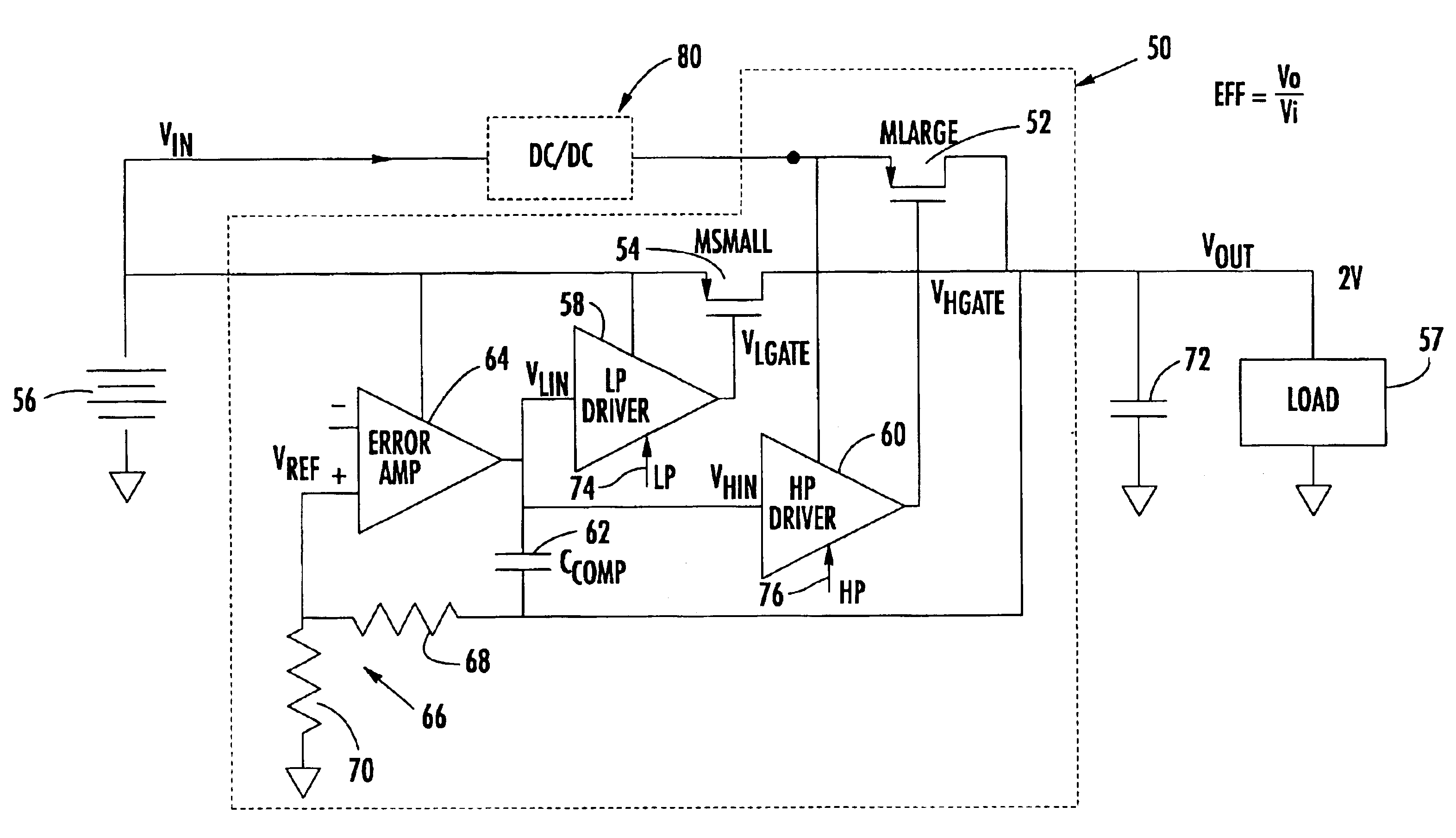
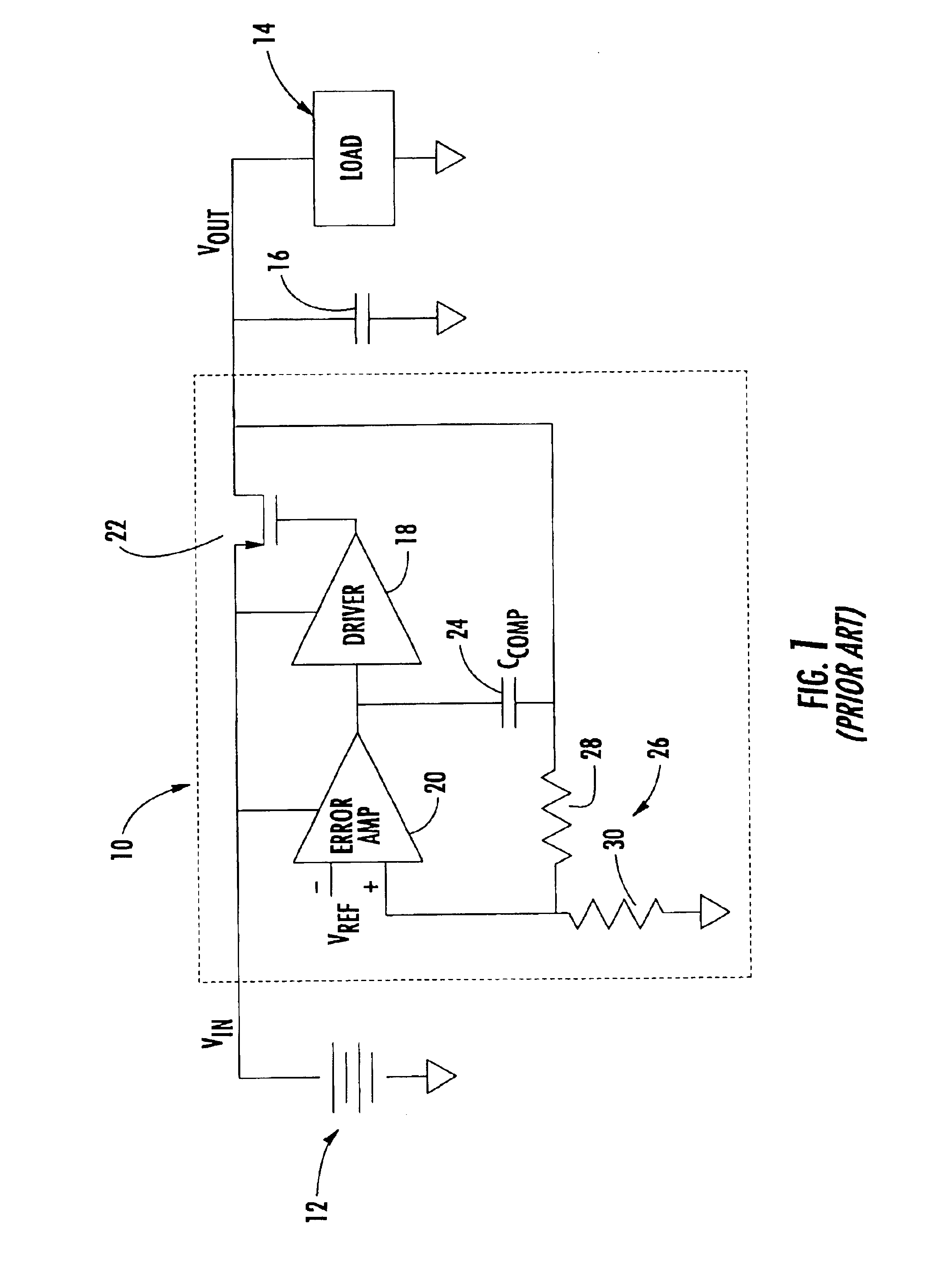
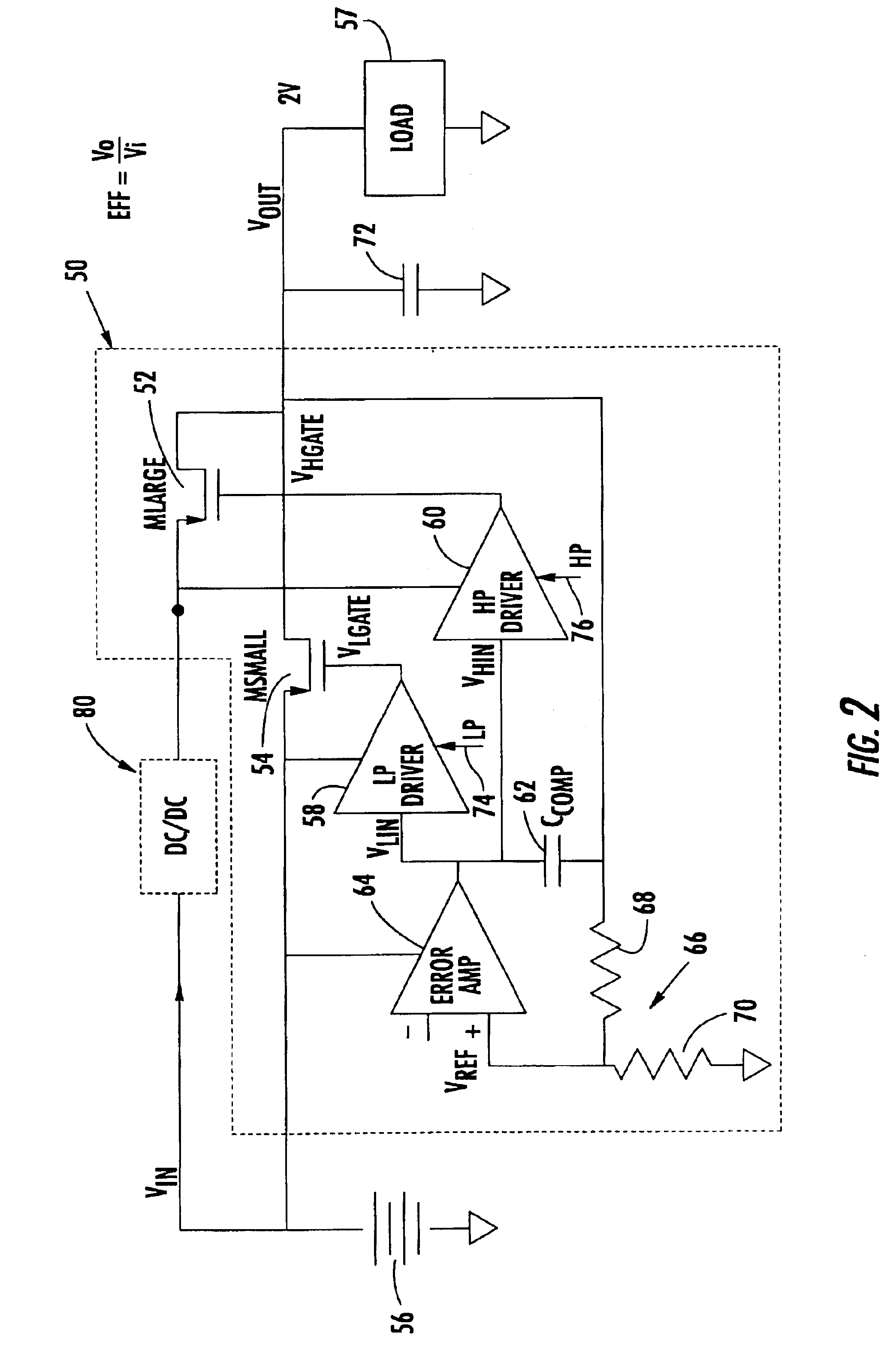
[0021]There is shown in FIG. 1 a conventional voltage regulator 10 which regulates the voltage between a power supply, battery, 12 and the load 14 which typically has associated with it a filter such as capacitor 16. Voltage regulators of the type of voltage regulator 10 are shown in U.S. Pat. No. 5,631,598 and include a single driver 18 and an error amplifier 20. Driver 18 operates a pass device such as MOSFET 22, connected between a power supply, battery, 12 and load 14. Output voltage Vout is a function of resistor divider 26, consisting of resistors 28 and 30, in the feedback loop consi...


PUM


Abstract

A multimode voltage regulator includes a low current pass device and a high current pass device each adapted for connection between a power supply and a load; an error amplifier responsive to a difference between a reference voltage and a function of the voltage on the load to produce an error signal; and a low power driver responsive in a low load power mode to an error signal for operating the low current pass device to provide low power to the load and a high power driver responsive in a high load power mode to an error signal for operating the high current pass device to provide high power to the load for maintaining efficiency over high and low power load operation.

Description

RELATED APPLICATIONS[0001]This application claims priority of U.S. Provisional Application Ser. No. 60 / 384,355 filed May 30, 2002.FIELD OF THE INVENTION[0002]This invention relates to a multimode voltage regulator for improving efficiency in both low and high power modes.BACKGROUND OF THE INVENTION[0003]Power supplies used in portable systems, such as Global System for Mobile Communications (GSM) mobile terminals, must be able to take advantage of the time varying nature of such systems. Typically, portable systems have an active state where the power supply is required to provide the full operating current (high power mode) and a standby state that requires minimal operating current (low power mode). For example, when the digital baseband engine in a GSM mobile terminal is actively processing data the power supply is required to provide the full operating current, but when the digital engine is not processing data the power supply is required to provide only leakage current. When a...

Claims


Application Information

Patent Timeline
Patent Type & Authority Patents(United States)
IPC IPC(8): G05F1/56G05F1/10H02M3/158H02M3/04G05F1/563G05F1/575G05F1/59
CPCG05F1/56G05F1/575H02M3/1584Y02B70/16H02M2001/0032H02M2001/0045H02M1/0032H02M1/0045Y02B70/10
Inventor BARBER, JR., THOMAS JAMESHO, STACYFERGUSON, JR., PAUL
Owner MEDIATEK INC
Why Eureka
Try Eureka