Probe assemblies for Raman spectroscopy

a raman spectroscopy and probe technology, applied in the field oframan spectroscopy, can solve the problems of inability to exhibit simple ir spectrum, inability to easily adapt to fiber optic data transmission, and inability to easily manufacture raman spectroscopy, and achieve the effect of convenient use with portable devices and easy manufacturing

Inactive Publication Date: 2005-05-24
RAMAN SYST
View PDF13 Cites 56 Cited by
  • Summary
  • Abstract
  • Description
  • Claims
  • Application Information

AI Technical Summary

Benefits of technology

[0009]The present invention provides Raman spectroscopy probe assemblies that are easy to manufacture and are particularly suitable for use with portable or even handheld analyzers. The probes of the present invention are also adaptable to sample liquids, tablets and / or powders and are capable of withstanding harsh environmental conditions. The probes can include an optical head assembly, associated optical fibers for irradiating a sample and capturing Raman scattered radiation, as well as replaceable sampling tubes.

Problems solved by technology

However, many liquids, especially aqueous solutions, do not exhibit simple IR spectrums.
Moreover, mid IR spectroscopy is not well suited for fiber optic data transmission.
Until recently, the major drawback of Raman spectroscopy has been its expense relative to mid IR and near IR spectroscopy systems.
A significant component of that expense is the monochromatic laser system required to produce quality, high-resolution spectra.
Even using a laser diode as the scattering source, the laser remains as one of the major expenses in developing cost-effective Raman systems.
The size and shape of conventional probes typically preclude incorporation of any safety features, such as shut-off switches, into the probe head, itself.
Moreover, in harsh process environments, conventional probes are also susceptible to damage by high temperatures, pressures and / or chemical solvents.

Method used


Image

  • Probe assemblies for Raman spectroscopy
  • Probe assemblies for Raman spectroscopy
  • Probe assemblies for Raman spectroscopy

Examples


Embodiment Construction

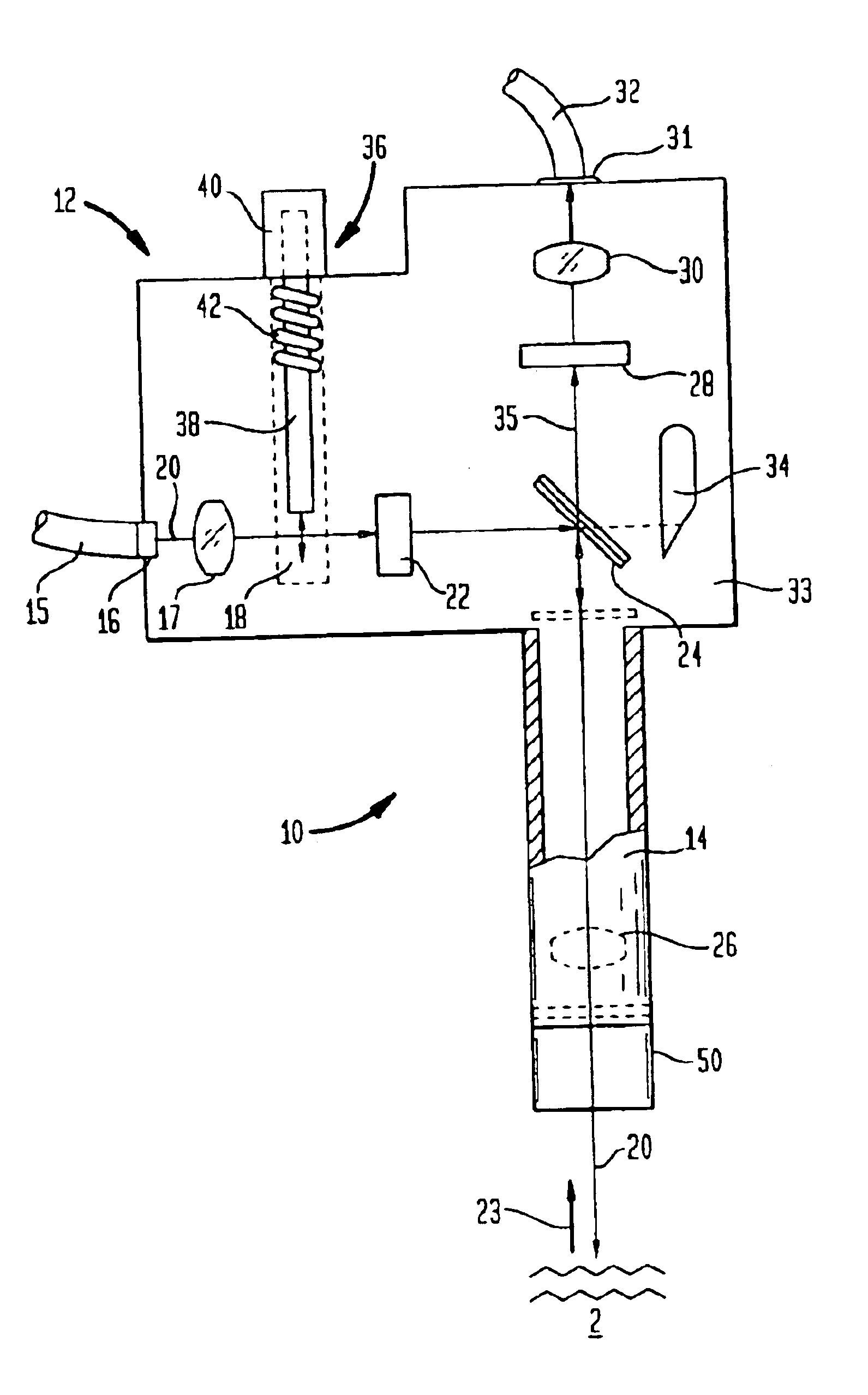
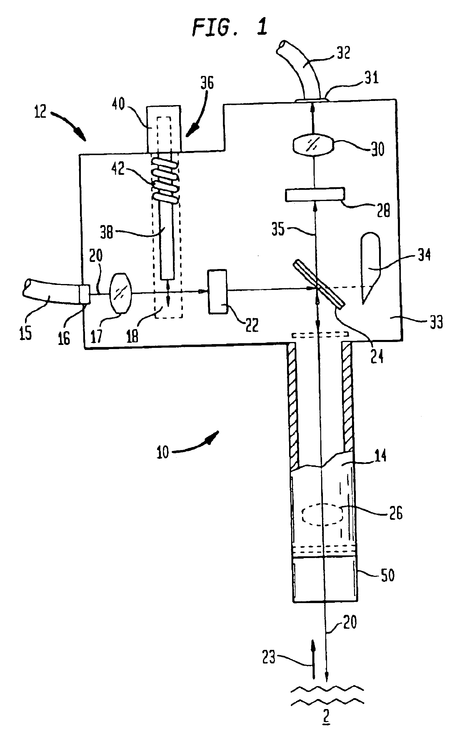
[0031]FIG. 1 is a schematic diagram of a probe 10 including an optical head assembly 12 and a sampling tube 14. Excitation radiation, e.g., from a portable or handheld Raman spectroscopy system, enters the head assembly 12 via input fiber 15. The input fiber can be coupled to the head assembly 12 via a coupler 16. The beam from the input fiber is passed through lens 17, which serves to collimate or other project the incoming radiation through the optical head assembly along beam path 20 with minimal dispersion. The radiation from the lens 17 then passes through chamber 18 of the safety switch 36. The incoming beam then passes through one or more optional filters 22, e.g., a low-pass filter.

[0032]The filtered incoming light is then reflected by dichroic beam-splitter 24 (which is designed to reflect nearly all of the excitation light) and directed into the sampling tube 14. Within sampling tube 14, a second lens 26 can be disposed to focus the excitation radiation to a particular poi...


PUM

PropertyMeasurementUnit
wavelengthaaaaaaaaaa

Abstract

Raman spectroscopy probe assemblies are disclosed for use with portable and/or handheld analyzers. The probes are also adaptable to sample liquids, and/or powders, tablets and/or other solids and are capable of withstanding harsh environmental conditions. The probes include an optical head assembly, associated optical fibers and replaceable sampling tubes. In one aspect of the invention, a simple orthogonal optical head assembly is disclosed that does not require collinear optical paths. The orthogonal arrangement of input and captured light paths also reduces the need for precise alignment of the optical components. The orthogonal optical head assemblies of the present invention are well suited to accommodate the shutoff mechanisms of the present invention. In another aspect of the invention, sampling tubes, and replaceable end caps for such tubes, are disclosed that facilitate hand measurements of substances.

Description

BACKGROUND OF THE INVENTION[0001]The technical field of this invention is Raman spectroscopy and, in particular, probes for analyzing samples in Raman spectroscopy systems.[0002]It is known in the art that the chemical analysis of materials can be determined by optical spectrum analysis of samples. The optical analysis can be based on near or mid infrared (IR) spectroscopy. However, many liquids, especially aqueous solutions, do not exhibit simple IR spectrums. Moreover, mid IR spectroscopy is not well suited for fiber optic data transmission.[0003]Raman spectroscopy provides an alternative approach to analyzing samples that is often better suited for aqueous and other liquid environments and, perhaps more generally, for applications where it is desirable to sample in-situ. Raman spectroscopy is an analytical technique that uses light scattering to identify and quantify molecules. When light of a single wavelength (monochromatic) interacts with a molecule, the light scattered by the...

Claims


Application Information

Patent Timeline
Patent Type & Authority Patents(United States)
IPC IPC(8): G01N21/27G01N21/65G01N21/25G01N21/63G01J3/44
CPCG01N21/276G01N21/65G01J3/44G01N2201/08G01N2201/06113
Inventor WOMBLE, M. EDWARDCLARKE, RICHARD H.
Owner RAMAN SYST
Why Eureka
Try Eureka