Printer and projector equipped with micromirror device

a technology of micromirror and projector, which is applied in the direction of digitally marking record carriers, printers, instruments, etc., can solve the problems of difficult to have a small printer, and achieve the effect of reducing size and high speed

Inactive Publication Date: 2005-05-31
FUJIFILM HLDG CORP +1
View PDF6 Cites 32 Cited by
  • Summary
  • Abstract
  • Description
  • Claims
  • Application Information

AI Technical Summary

Benefits of technology

[0007]In view of the foregoing problems, an object of the present invention is to provide a printer and projector which is equipped with a micromirror device, can have a size reduced by a structural improvement, and can operate at high speed.

Problems solved by technology

The printer is difficult to have a small size, as the necessity of the two light sources is inconsistent to reducing the size of the printer.

Method used


Image

  • Printer and projector equipped with micromirror device
  • Printer and projector equipped with micromirror device
  • Printer and projector equipped with micromirror device

Examples


Embodiment Construction

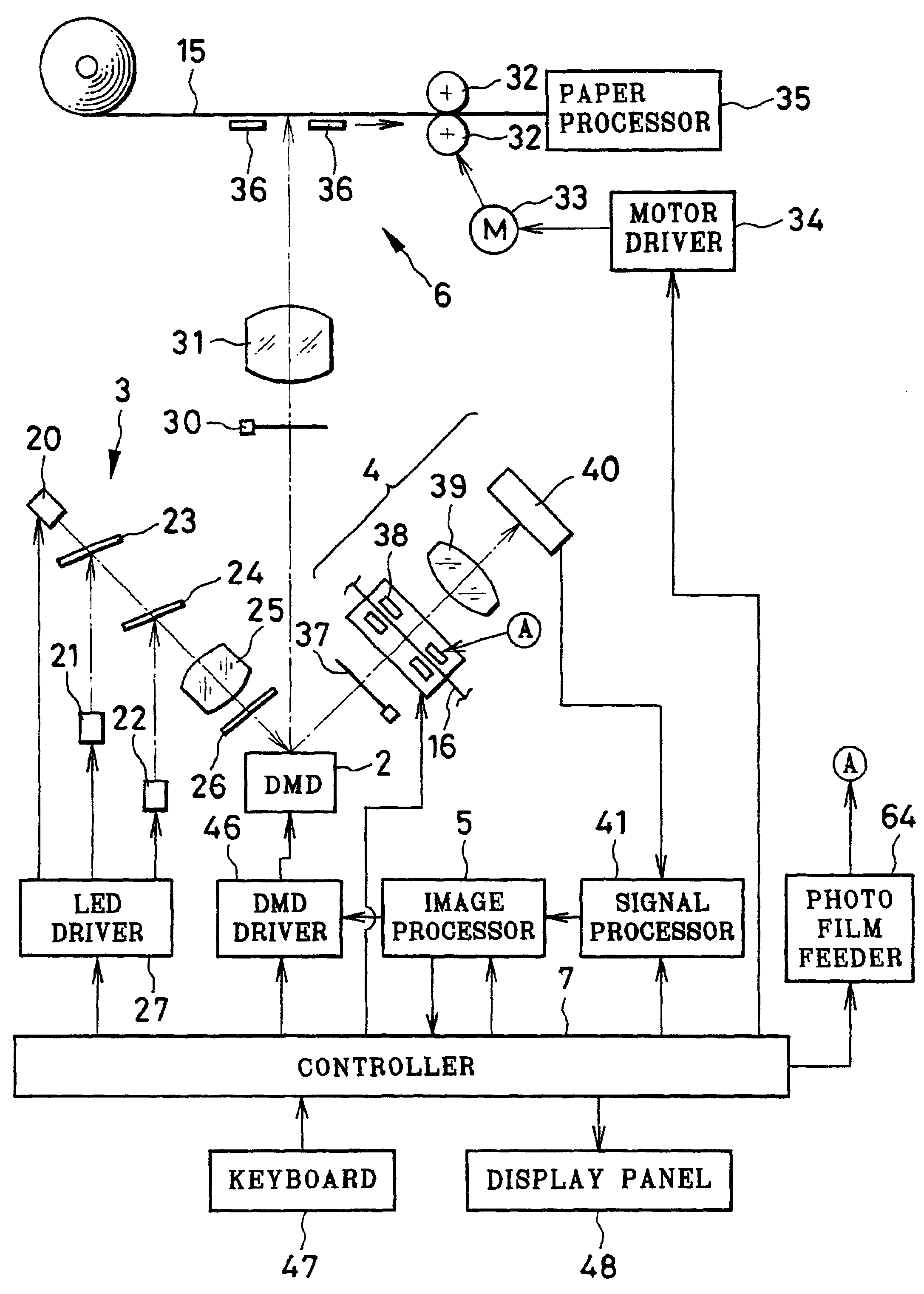
[0028]In FIG. 1, a printer of the present invention is depicted, and includes a digital micromirror device (DMD) 2 as spatial light modulator, an LED light source set 3, a pick-up section 4, an image processor 5, a paper exposure section 6 and a controller 7.

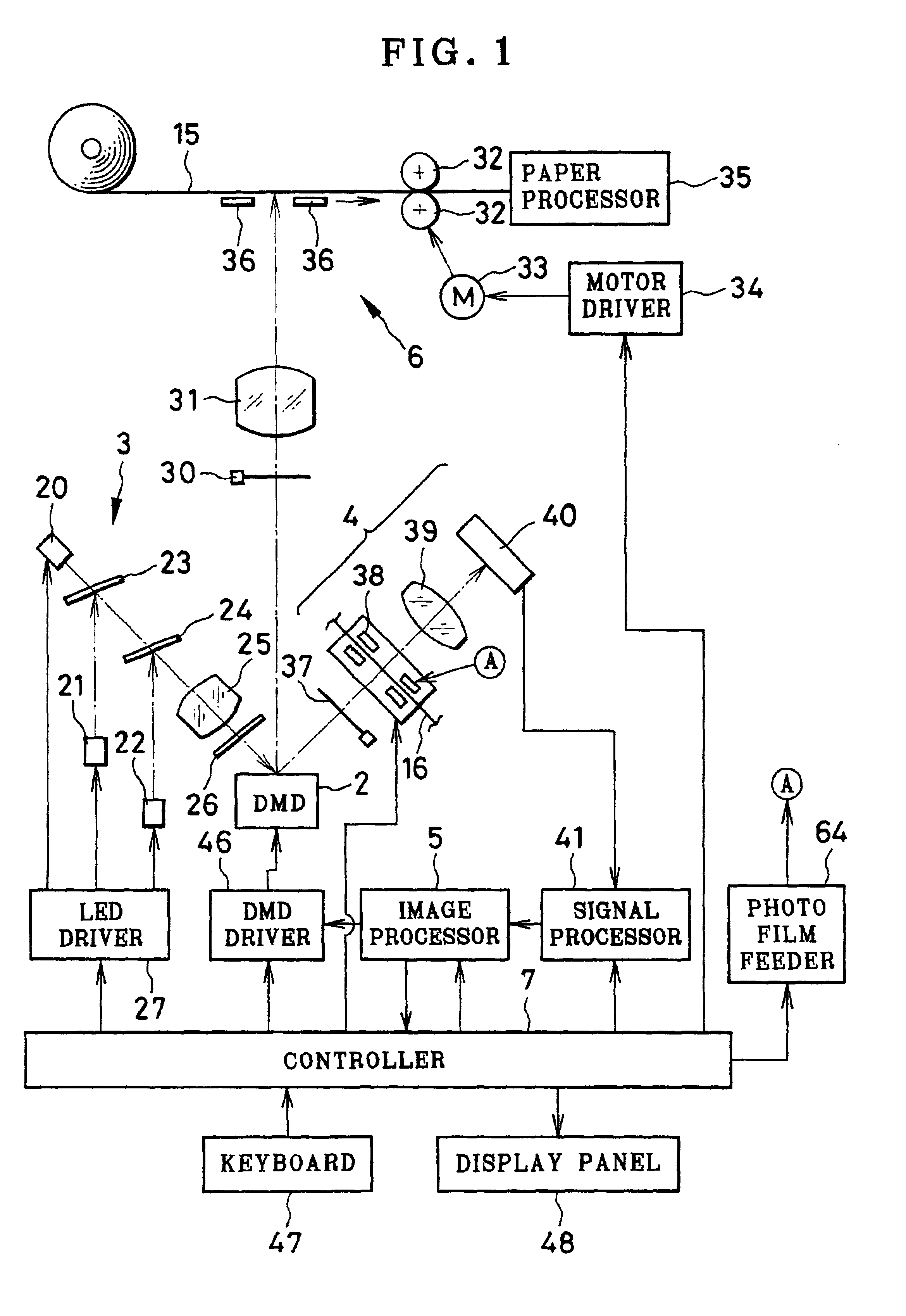
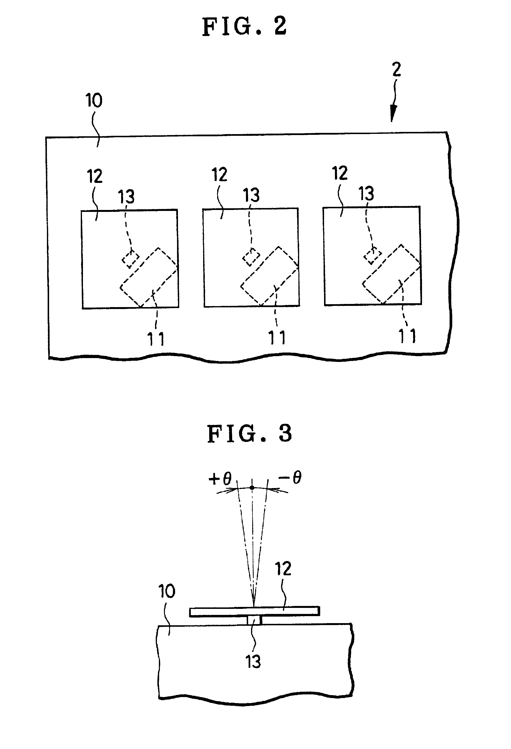
[0029]In FIG. 2, a construction of the digital micromirror device 2 is illustrated. The digital micromirror device 2 includes static RAM (SRAM) 10, micromirrors 12 and posts 13. The static RAM 10 is constituted by a great number of memory cells 11 arranged in a matrix form. The micromirrors 12 in a small size are disposed on respectively the memory cells 11, and supported by the posts 13 in a pivotally movable manner. The micromirrors 12 have a quadrilateral shape of which each side is 16 μm long, and are formed of thin film of metal with electrical conductivity, for example of aluminum or the like. The micromirrors 12 are tilted by electrostatic force generated between the micromirrors 12 and the memory cells 11. The memory cel...


PUM


Abstract

A printer includes an image area sensor for picking up a picture frame in photo film to output image data. A printing projecting lens focuses and records a print frame to color photographic paper. Three LED light sources generate light. A digital micromirror device (DMD) is disposed in a traveling path of the light, includes plural micromirrors arranged in at least one array. The plural micromirrors are individually shiftable between first and second positions different in a direction, and when in the first position, direct the light to the photo film by reflection, and when in the second position, direct the light to the printing projecting lens by reflection. A controller initially sets the plural micromirrors in the first position, to illuminate the picture frame in the photo film while the image area sensor is operated. According to the image data, the controller sets micromirrors in one first group in the DMD to the first position, and sets micromirrors in a second group in the DMD to the second position except for the first group, to modulate the light by reflection on the second group. Thus, the print frame is printed with the printing projecting lens.

Description

BACKGROUND OF THE INVENTION[0001]1. Field of the Invention[0002]The present invention relates to a printer and projector equipped with a micromirror device. More particularly, the present invention relates to a printer and projector which is equipped with a micromirror device, can have a small size and can operate at high speed.[0003]2. Description Related to the Prior Art[0004]An example of printer is a color photographic printer, which prints an image to photographic paper as photosensitive material, the image being obtained from negative photo film. Examples of the printer includes an analog printing type and digital printing type. In the analog printing type, light transmitted through the photo film is directly projected to the photographic paper. The digital printing type utilizes a cathode ray tube (CRT), laser, liquid crystal or the like. In the printer with the laser or liquid crystal, there is a spatial light modulator, which modulates three-color light emitted from a light...

Claims


Application Information

Patent Timeline
Patent Type & Authority Patents(United States)
IPC IPC(8): B41J2/435B41J2/465G02B26/08B41J2/44G03B27/32H01L33/60H04N1/113H04N1/23
CPCG02B26/0841B41J2/465
Inventor KITO, EIICHI
Owner FUJIFILM HLDG CORP
Why Eureka
Try Eureka