FED cathode structure using electrophoretic deposition and method of fabrication

Inactive Publication Date: 2005-06-07
MOTOROLA SOLUTIONS INC
View PDF11 Cites 66 Cited by
  • Summary
  • Abstract
  • Description
  • Claims
  • Application Information

AI Technical Summary

Benefits of technology

[0008]The above problems and others are at least partially solved and the above purposes and others are realized in an FED cathode structure and method of fabricating an FED cathode structure using electrophoretic deposition of carbon nanotubes in which a separate step of a depositing a binder material on a substrate, is performed prior to carbon nanotube particle deposition. The binder is necessary in EPD to glue the particles to the substrate. First, a binder layer is formed on a substrate, when the substrate is deposited in a solution such as Mg(NO3)2 / IPA. The substrate having the binder material formed thereon is then transferred into a carbon nanotube (CNT) suspension bath allowing for coating of the CNT particles onto the binder layer. Thermal processing of the binder layer and CNT particle coating transforms the Mg(OH)2 into MgO. In one particular embodiment a plurality of micro-island structures are formed. The MgO serves as a ballast layer for uniform emission since it is not a good conductor. Additionally, the thermal processing embeds the CNT particles to the binder material. Post-deposition activation, such as mechanical polishing is not required to obtain a high density of emission sites in the presence of the MgO binder separating into micro-islands upon thermal processing, with CNTs protruding from the edges of the islands.

Problems solved by technology

The MgO serves as a ballast layer for uniform emission since it is not a good conductor.

Method used


Image

  • FED cathode structure using electrophoretic deposition and method of fabrication
  • FED cathode structure using electrophoretic deposition and method of fabrication
  • FED cathode structure using electrophoretic deposition and method of fabrication

Examples


Embodiment Construction

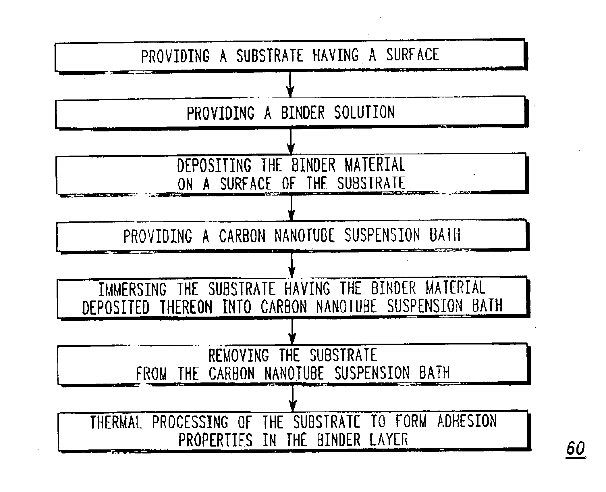
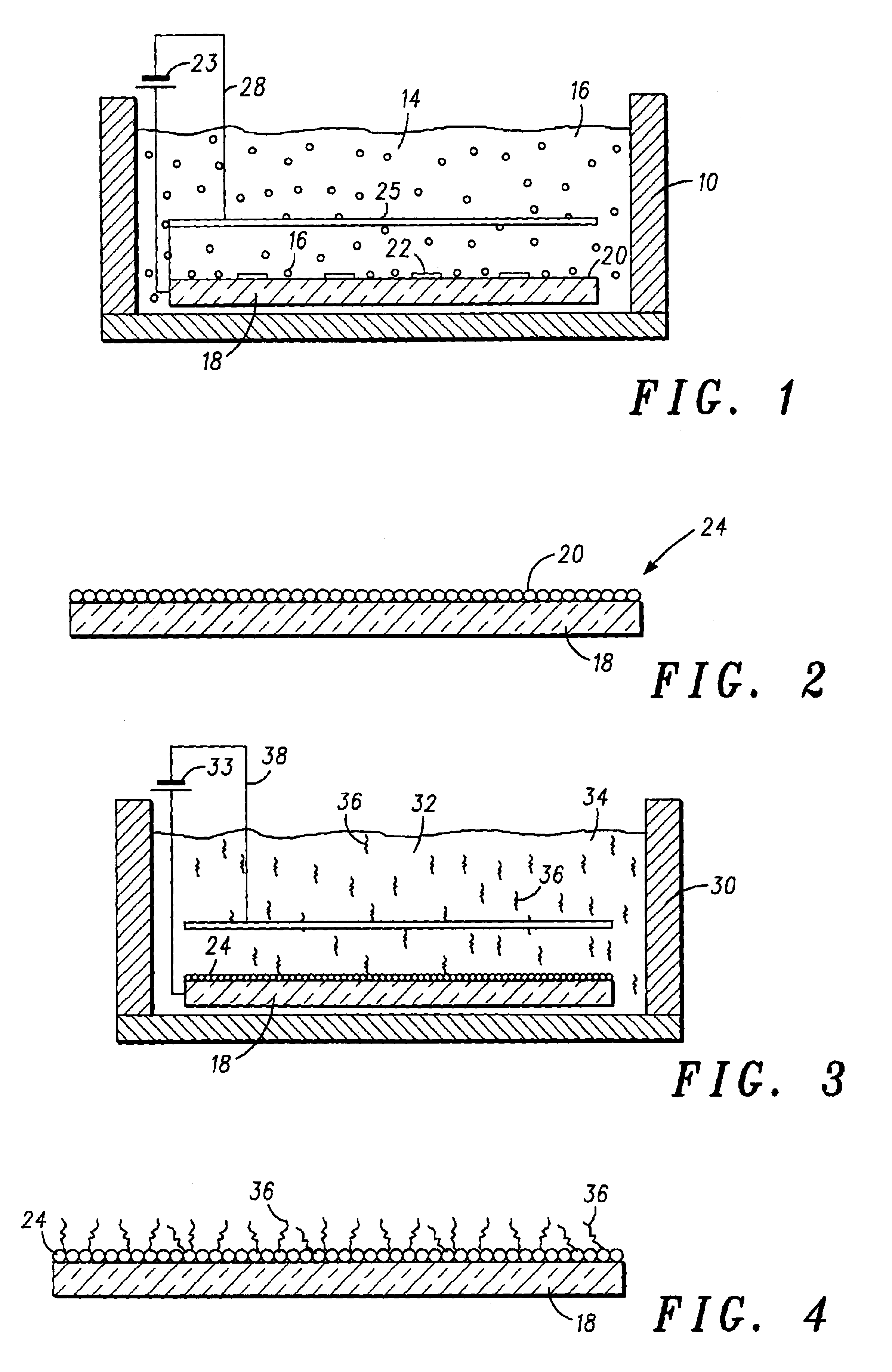
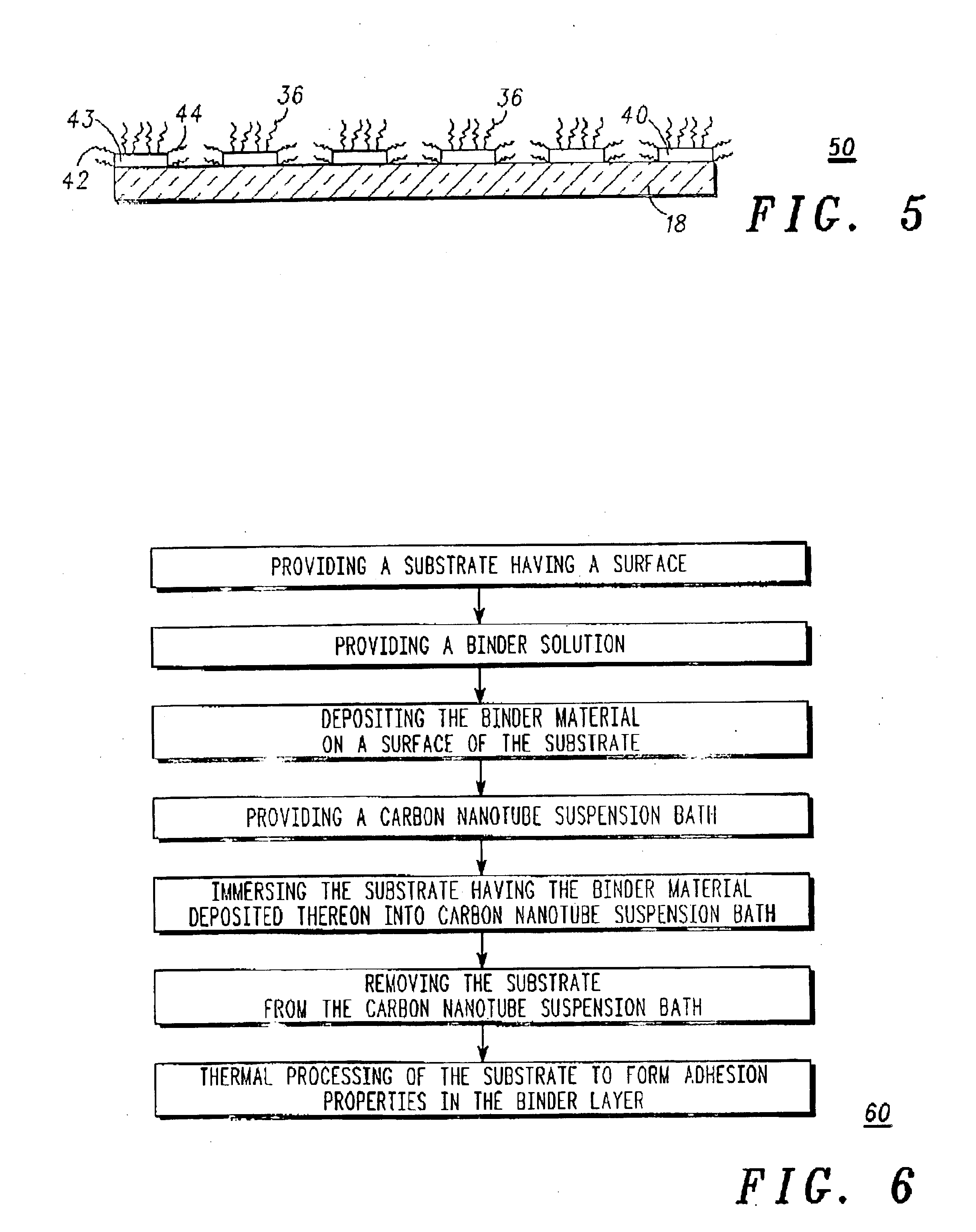
[0013]This invention describes a field emission cathode structure and a new method of fabricating the field emission cathode structure utilizing electrophoretic deposition (EPD) of particles from a suspension. A process especially suited for carbon nanotube (CNT) deposition is given as an example. The new method of fabricating the cathode structure includes the separation of the binder deposition as a separate step which is performed prior to the carbon nanotube particle deposition. The binder is necessary in EPD to glue the carbon nanotube particles to the substrate. The prior art provides for the deposition of the binder concomitantly with the particle deposition. As previously stated, a stable colloidal suspension, which is desirable for uniform films, is not always obtainable with the binder material and the powder together in the same solution. This is exemplified in the case of CNT in suspension in the presence of cations. For example, a stable suspension of CNT in isopropyl a...


PUM

PropertyMeasurementUnit
temperatureaaaaaaaaaa
adhesion propertiesaaaaaaaaaa

Abstract

A method of fabricating a field emission device cathode using electrophoretic deposition of carbon nanotubes in which a separate step of depositing a binder material onto a substrate, is performed prior to carbon nanotube particle deposition. First, a binder layer is deposited on a substrate from a solution containing a binder material. The substrate having the binder material deposited thereon is then transferred into a carbon nanotube suspension bath allowing for coating of the carbon nanotube particles onto the substrate. Thermal processing of the coating transforms the binder layer properties which provides for the adhesion of the carbon nanotube particles to the binder material.

Description

FIELD OF INVENTION[0001]The present invention pertains to field emission display devices, and more particularly to a novel field emission cathode structure and method of forming the field emission cathode structure for use in a field emission display device.BACKGROUND OF THE INVENTION[0002]Field emission devices (FEDs) are known in the art. Such prior art devices are constructed by a variety of methods all of which yield structures with the purpose of emitting electrons from an emitter electrode. FEDs typically include an anode, a cathode, and phosphors disposed therebetween in a position corresponding to each pixel. During operation, electrons emitted by the cathode, are accelerated by an electric field created between the cathode and the anode, and impinge upon the phosphors, thereby exciting the phosphors to emit light, and thus display an image.[0003]It is known in the prior art to form cathode structures utilizing carbon nanotube (CNT) deposition. Typically, during cathode fabr...

Claims


Application Information

Patent Timeline
Patent Type & Authority Patents(United States)
IPC IPC(8): H01J1/304H01J1/30H01J9/02
CPCB82Y10/00B82Y30/00H01J9/025H01J1/3042C25D13/02
Inventor TALIN, ALBERT ALECDEAN, KENNETH ANDREWO'ROURKE, SHAWN M.COLL, BERNARD F.STAINER, MATTHEWSUBRAHMANYAN, RAVICHANDRAN
Owner MOTOROLA SOLUTIONS INC
Why Eureka
Try Eureka