
Open-channeled spiral-wound membrane module

a membrane module and spiral-wound technology, applied in the field of spiral-wound membrane modules, can solve the problems of membrane fouling, hollow fiber membrane design, and inability to use, and achieve the effect of reducing fluid flow resistan

Inactive Publication Date: 2005-06-07
HYDRATION SYST
View PDF19 Cites 7 Cited by
  • Summary
  • Abstract
  • Description
  • Claims
  • Application Information

AI Technical Summary

Benefits of technology

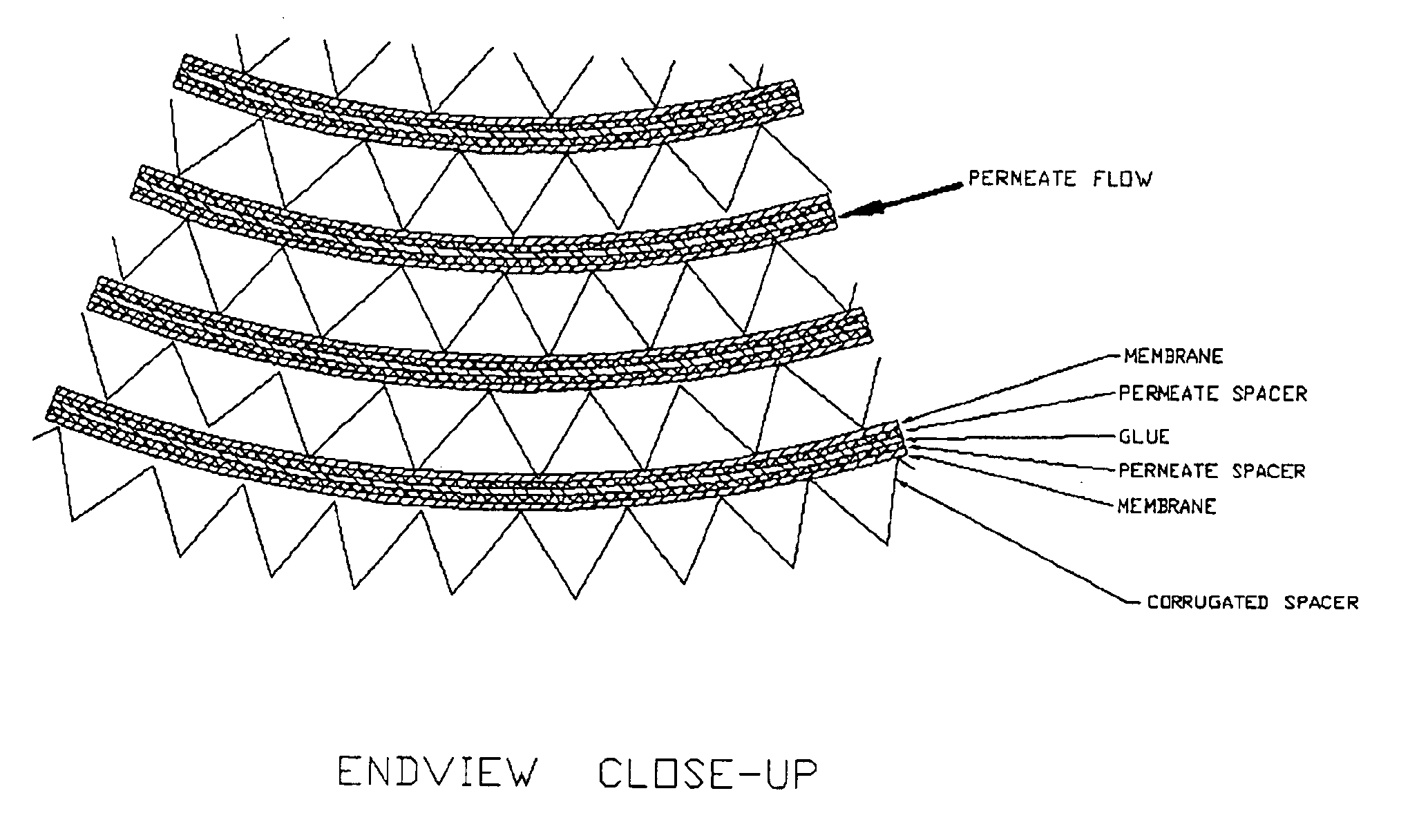
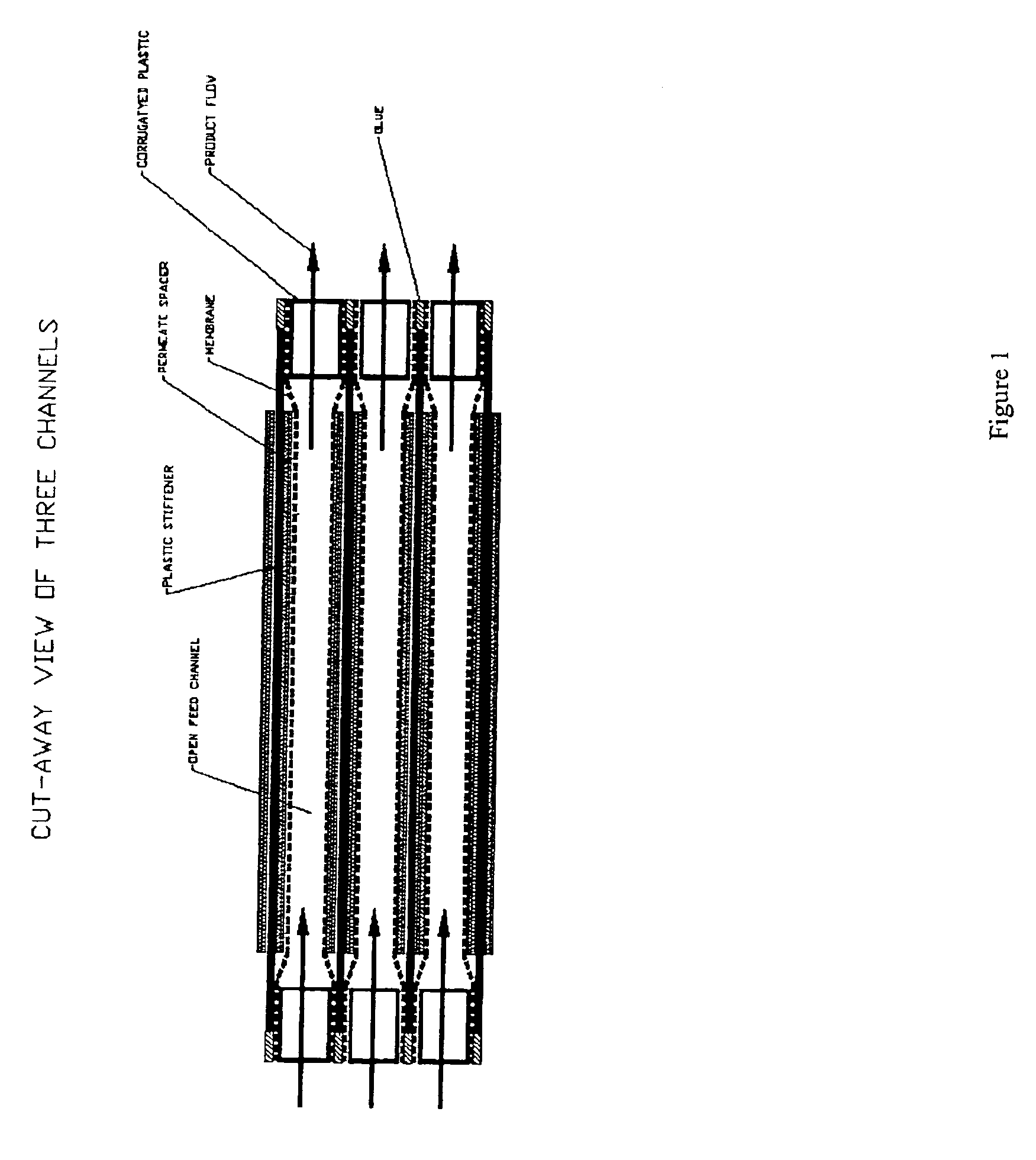
[0007]The present invention provides a spiral wound membrane module having a length and a radius and a circular cross section, having reduced fluid flow resistance, comprising:
[0013](a) assembling an envelope sandwich having a width equal to the length of the membrane module and comprising a layer of membrane next to a layer of permeate spacer material next to a layer of stiffener means next to a layer of permeate spacer material next to a layer of membrane, and wherein the envelope sandwich is wrapped increasing the radius of the membrane module;

Problems solved by technology

In the field of pressure-driven membrane separations (e.g., ultrafiltration, reverse osmosis, nanofiltration) there is frequently a problem of membrane fouling from contamination of other dissolved and suspended solids in feed streams.
However, hollow fiber membrane designs will foul most easily and cannot be used for the majority of feed streams in industrial processing or waste treatment due to fouling problems.
The next most expensive membrane design in terms of providing the greatest membrane surface area in a vessel per cost is a spiral wound configuration.
Spiral wound membrane designs have been used successfully but can also foul with higher fouling feed streams.
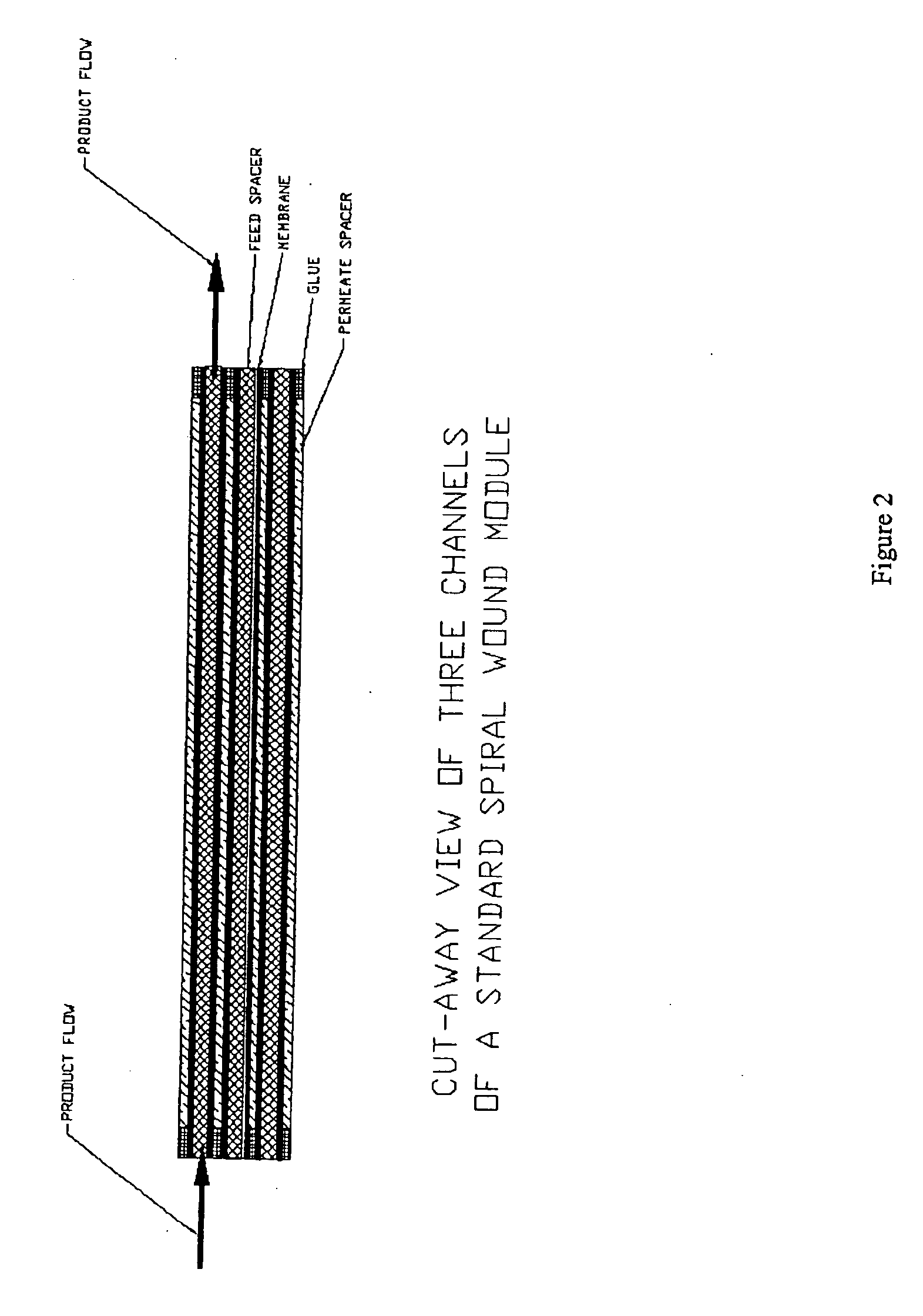
The fouling problem in standard spiral wound membranes is often due to the nature of the feed spacer that is required to be located through each of the feed channels.
Therefore, spiral wound membrane designs can also have fouling problems in the feed spacer and membrane and incur significant fluid dynamic problems due to resistance of the feed spacer.
A tubular design provides the least amount of membrane surface area per module length, and is most expensive to manufacture due to labor intensive procedures for “potting” the tubular membranes within a module.
Moreover, the inlet and outlet chambers associated with tubular designs are also most expensive.

Method used


Image

  • Open-channeled spiral-wound membrane module
  • Open-channeled spiral-wound membrane module
  • Open-channeled spiral-wound membrane module

Examples


Embodiment Construction

[0023]The present invention provides an improved membrane design for spiral wound membranes that provide the cost advantages and space savings of spiral wound with superior flux and fouling characteristics. The advantage of a spiral wound membrane design prior to the present invention is that it is inexpensive and has high membrane density (˜30 m2 per 20 cm diameter by 100 cm long element). Its drawback is that it is highly susceptible to fouling since the feed must flow longitudinally through a net-like feed spacer. The fibers of the feed spacer allow suspended solids to become lodged and blind the membrane, degrading performance and inhibiting cleaning. Pressure drops are also high in the flow through the feed spacer, which makes it impossible to achieve the fluid velocities that have been shown to provide the best performance of membranes.

[0024]Another membrane module design in common usage is the “tubular” design. In this design, the fluid is pumped at high velocity down the cen...


PUM

PropertyMeasurementUnit
Fractionaaaaaaaaaa
Fractionaaaaaaaaaa
Thicknessaaaaaaaaaa

Abstract

There is disclosed a spiral-wound membrane module design for various membrane filtration techniques having significantly reduced fluid flow resistance in the feed stream path. Specifically, the inventive spiral-wound membrane module is designed having a corrugated entrance and exit spacers together over less than 10% of the length of the spiral wound module and a stiffener sheet wound to provide for uniform feed channel gap width.

Description

[0001]This is a Provisional of application Ser. No. 09 / 688,612, filed Oct. 15, 2000, now U.S. Pat. No. 6,673,242.TECHNICAL FIELD OF THE INVENTION[0002]The present invention provides a spiral-wound membrane module design for various membrane filtration techniques having significantly reduced fluid flow resistance in the feed stream path. Specifically, the inventive spiral-wound membrane module is designed having a corrugated entrance and exit spacers together over less than 10% of the length of the spiral wound module and a stiffener sheet wound to provide for uniform feed channel gap width.BACKGROUND OF THE INVENTION[0003]In the field of pressure-driven membrane separations (e.g., ultrafiltration, reverse osmosis, nanofiltration) there is frequently a problem of membrane fouling from contamination of other dissolved and suspended solids in feed streams. This kind of membrane separation has been used, for example, in apple juice clarification, waste water treatment, cheese whey desal...

Claims


Application Information

Patent Timeline
IPC IPC(8): B01D63/10
CPCB01D63/10Y10S264/48B01D63/103
Inventor HERRON, JACK
Owner HYDRATION SYST
Learn More