Circuit for driving a stepper motor and method of controlling a stepper motor driver

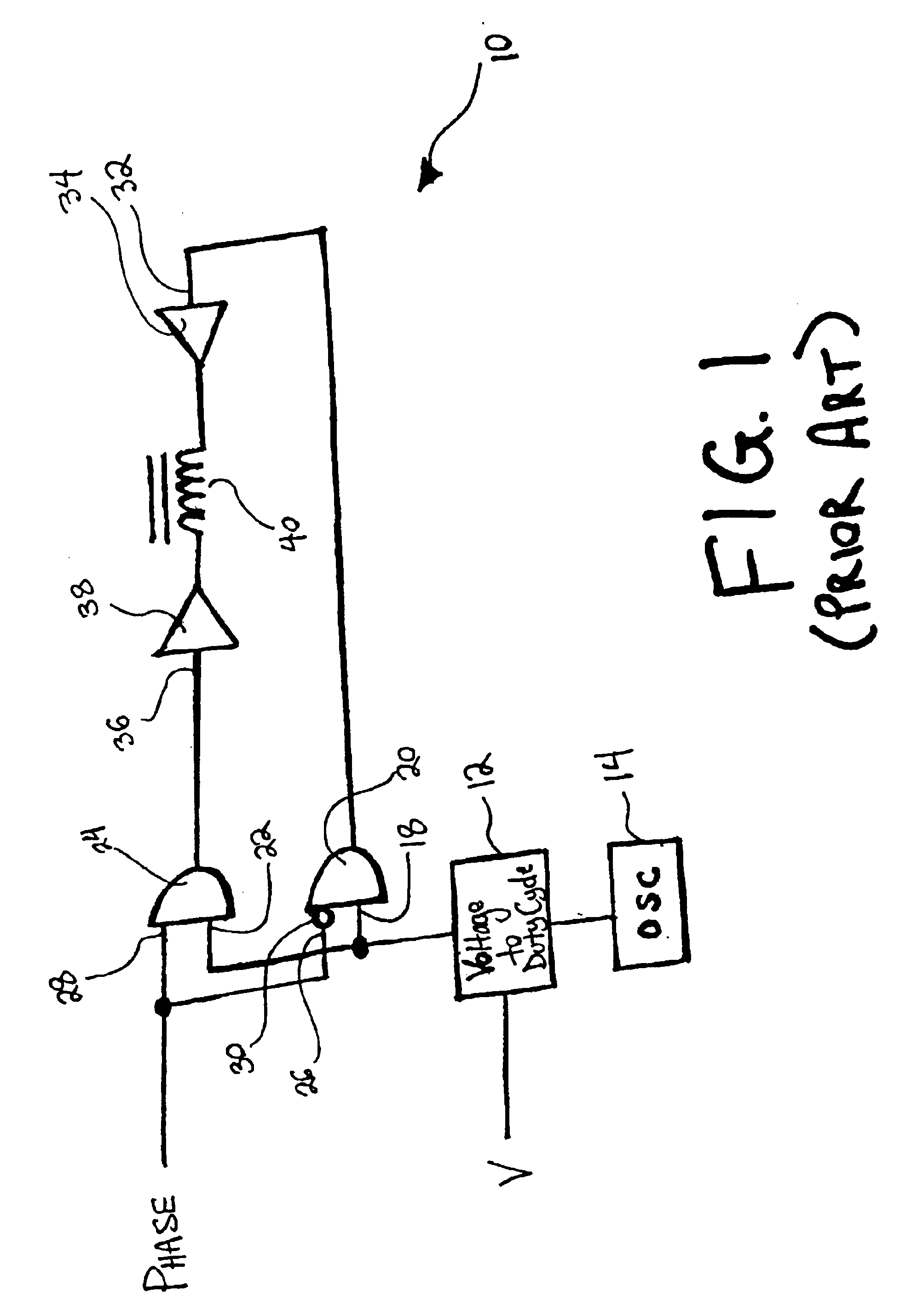
a stepper motor and stepper motor technology, applied in the direction of electric controllers, dynamo-electric converter control, instruments, etc., can solve the problems of noise, one disadvantage experienced, and the conventional circuit b>10/b> experiences several, and achieve the effect of eliminating the operation noise of the motor

Inactive Publication Date: 2005-06-07
ELECTRONIC THEATRE CONTROLS
View PDF14 Cites 5 Cited by
  • Summary
  • Abstract
  • Description
  • Claims
  • Application Information

AI Technical Summary

Benefits of technology

[0012]The above-listed objects are met or exceeded by the present driver circuit for a stepper motor system. Major advantages of this circuit include an open-loop system, and a switching circuit which can provide both PWM phase inversion and PWM loss protection through the hardware of the circuit itself. The driving method for the motor additionally corrects for significant anomalies experienced by conventional motor systems.
[0016]Under normal motor loads and standard driving speeds, the present invention is particularly effective at eliminating operational noise from the motor, while also allowing the motor to operate smoothly over a continuous range of operational speeds.

Problems solved by technology

Such conventional circuits experience several disadvantages in operation.
One disadvantage experienced by the conventional circuit 10 is noise.
Imprecise frequency control of the oscillator causes an undesirable audible frequency jitter, or “fizzing.” Furthermore, long wires in the feedback network connected to the stepper motor windings cause an undesirable electrical ringing noise, which can also occur audibly.
Another disadvantage experienced by the circuit 10 occurs when the phase control is switched.
The non-uniform rotation results in an increased vibration in the motor, which further increases the audible noise experienced.
Still another disadvantage experienced with the circuit 10 rises out of the fact that H-bridges experience a “dead zone” when the voltage driving the motor windings 40 crosses through zero.
The dead zone causes a noticeable and undesirable pause of the motor motion at slow shaft speeds.
The pause results in a jerky shaft rotation of the motor, which makes precise positioning of the motor shaft difficult to impossible at a dead zone location.
The dead zone crossings also further increase the generated noise experienced by the motor.
Although useful for balancing the duty cycle of the PWM signal, the discrete, single-speed operating method described by Peeters is unable to compensate for different, or variable, operational drive speeds.
This method is also unable to compensate for dead zone anomalies within a drive step, and therefore cannot accurately position the motor at lower drive speeds, where the inertia of the system is weaker, and thus unable to mask the dead zone anomalies.
Similar to Peeters though, Labriola also requires dynamic measurements of some variables with a closed-loop feedback system that can produce undesirable noise.

Method used


Image

  • Circuit for driving a stepper motor and method of controlling a stepper motor driver
  • Circuit for driving a stepper motor and method of controlling a stepper motor driver
  • Circuit for driving a stepper motor and method of controlling a stepper motor driver

Examples


Embodiment Construction

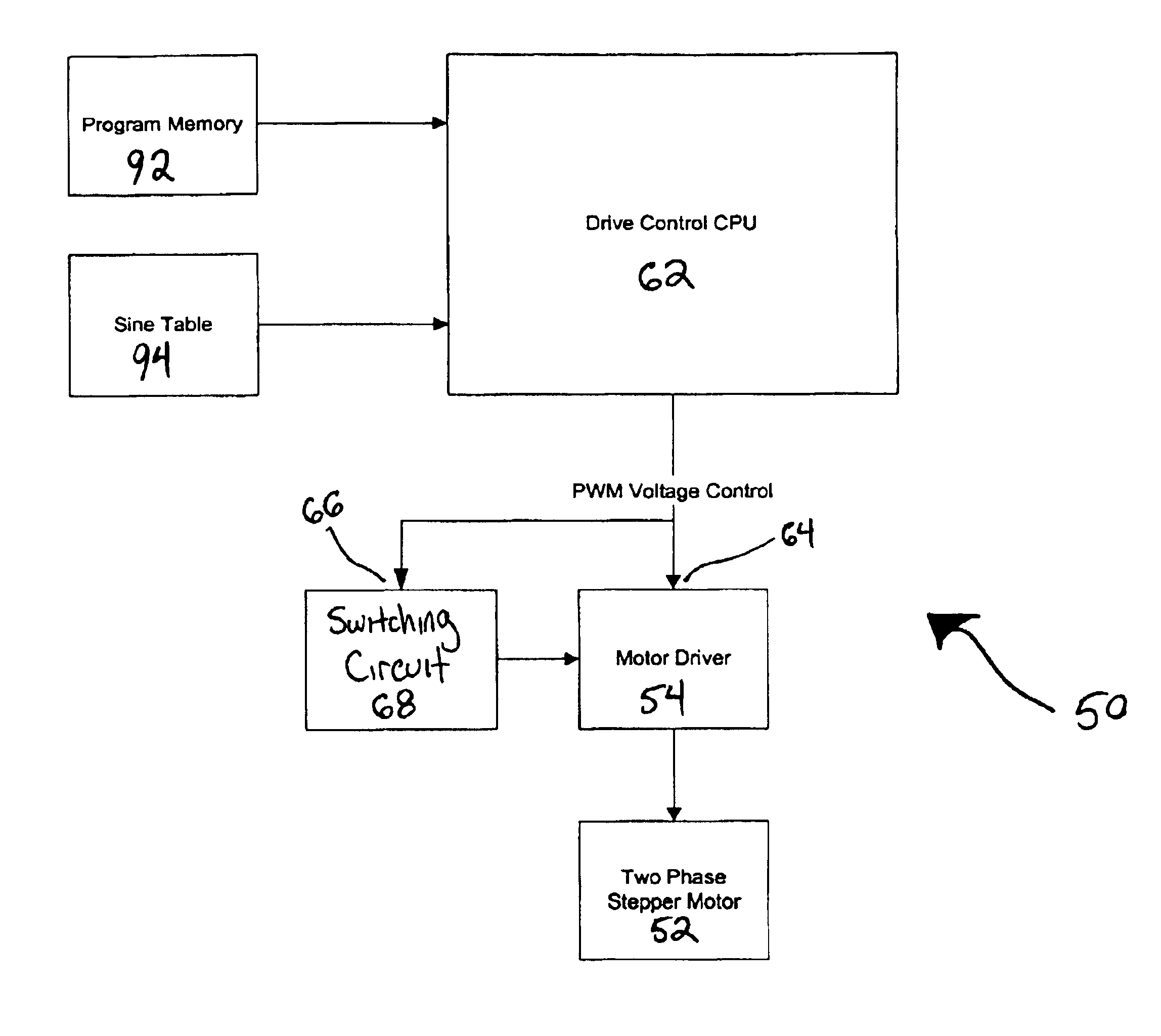
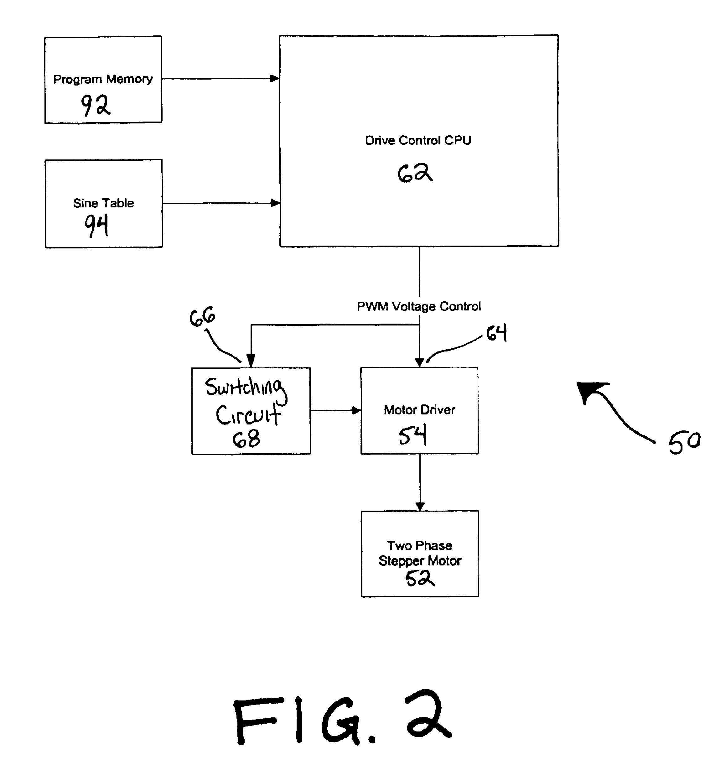
[0021]Referring now to FIGS. 2 and 3, a stepper motor system of the type suitable for use in the present invention is generally designated 50, and includes a stepper motor 52 and a motor driver 54 for driving the stepper motor. The stepper motor 52 is preferably a two-phase motor, and the motor driver 54 is preferably an H-bridge circuit, as are known in the art. The motor driver 54 includes separate first and second drivers 56 and 58, respectively, for driving both respective ends of a motor winding 60 of the two-phase motor 52. A PWM voltage control signal is applied directly from a drive control CPU 62 to an input 64 to the first driver 56 of the motor driver 54, as best seen in FIG. 3.

[0022]The same PWM signal is also applied directly from the CPU 62 to an input 66 of a switching circuit 68. The switching circuit 68 preferably includes an exclusive OR gate 70 and a charge pump 72 as its main components. A first input 74 of the exclusive OR gate 70 connects directly to the switch...


PUM


Abstract

A driver circuit is provided for a stepper motor which utilizes a processor that outputs a PWM signal. The driver circuit includes an H-bridge circuit having first and second inputs, and a switching circuit having an input and an output. The first H-bridge input and the switching input connect to the PWM signal output from the processor, and the switching output connects to the second H-bridge input. The switching circuit performs an inversion of a duty cycle of the PWM signal when the PWM signal is present, and a non-inversion of the duty cycle when the PWM signal is not present.

Description

BACKGROUND OF THE INVENTION[0001]The present invention relates to stepper motors systems in general, and more specifically to an improved circuit for driving a stepper motor and a method of controlling the circuit and driver.[0002]Stepper motor systems and drivers are known in the art. Conventional stepper motor systems include a stepper motor and a driver for the motor, the motor driver typically including an H-bridge circuit. FIG. 1 illustrates a conventional circuit 10 for driving a stepper motor.[0003]An analog voltage signal is fed into a voltage-to-duty-cycle converter 12, which is clocked by an oscillator 14. An output of the converter 12 is then fed into a first input 18 of a first AND gate 20, and into a first input 22 of a second AND gate 24. A phase signal is fed into second respective inputs 26, 28 of the first and second AND gates 20, 24. The phase signal into the second input 26 is first passed through an inverter 30. An output of the first AND gate 20 is then fed into...

Claims


Application Information

Patent Timeline
Patent Type & Authority Patents(United States)
IPC IPC(8): H02P8/00H02P8/12H02P8/22
CPCH02P8/22H02P8/12
Inventor SUOMI, ERIC W.STANKEY, THOMAS M.
Owner ELECTRONIC THEATRE CONTROLS
Why Eureka
Try Eureka