Low noise intracavity laser particle counter

Active Publication Date: 2005-06-07
PARTICLE MEASURING SYST
View PDF12 Cites 69 Cited by
  • Summary
  • Abstract
  • Description
  • Claims
  • Application Information

AI Technical Summary

Benefits of technology

[0011]The present invention advances the art and helps to overcome the aforementioned problems by providing a system which combines high power operation with effective noise reduction to enable efficient counting of very small particles in an OPC. The invention provides an optical particle counter that includes both gain aperturing and an optical barrier that physicall

Problems solved by technology

In particular, it has been found that turbulent eddies breaking off the fluid inlet jet

Method used


Image

  • Low noise intracavity laser particle counter
  • Low noise intracavity laser particle counter
  • Low noise intracavity laser particle counter

Examples


Embodiment Construction

[0032]In this disclosure, the term “light” is not limited to visible radiation but is used in a broad sense meaning any electromagnetic radiation. In this disclosure, laser light emerging directly from a laser apparatus is “original laser light”; and laser light reflected by a laser cavity end mirror is “reflected laser light”.

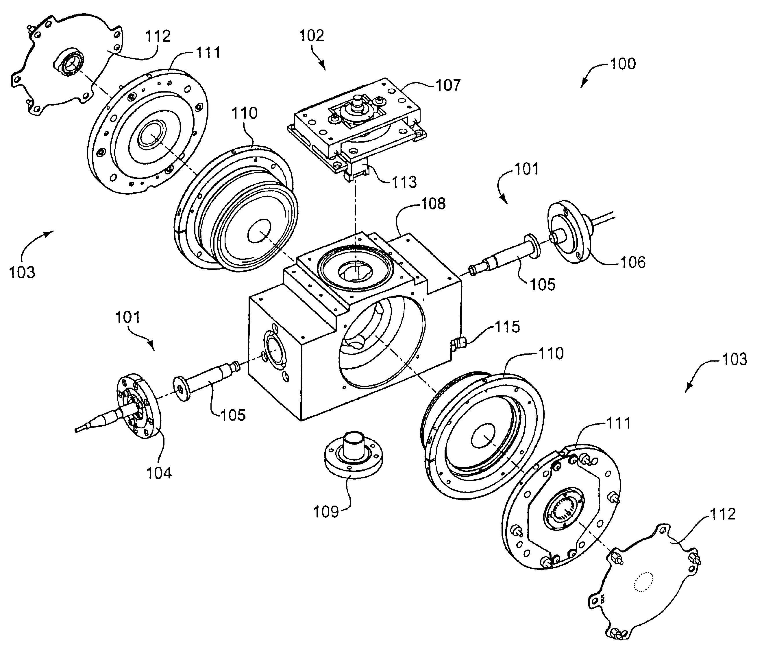
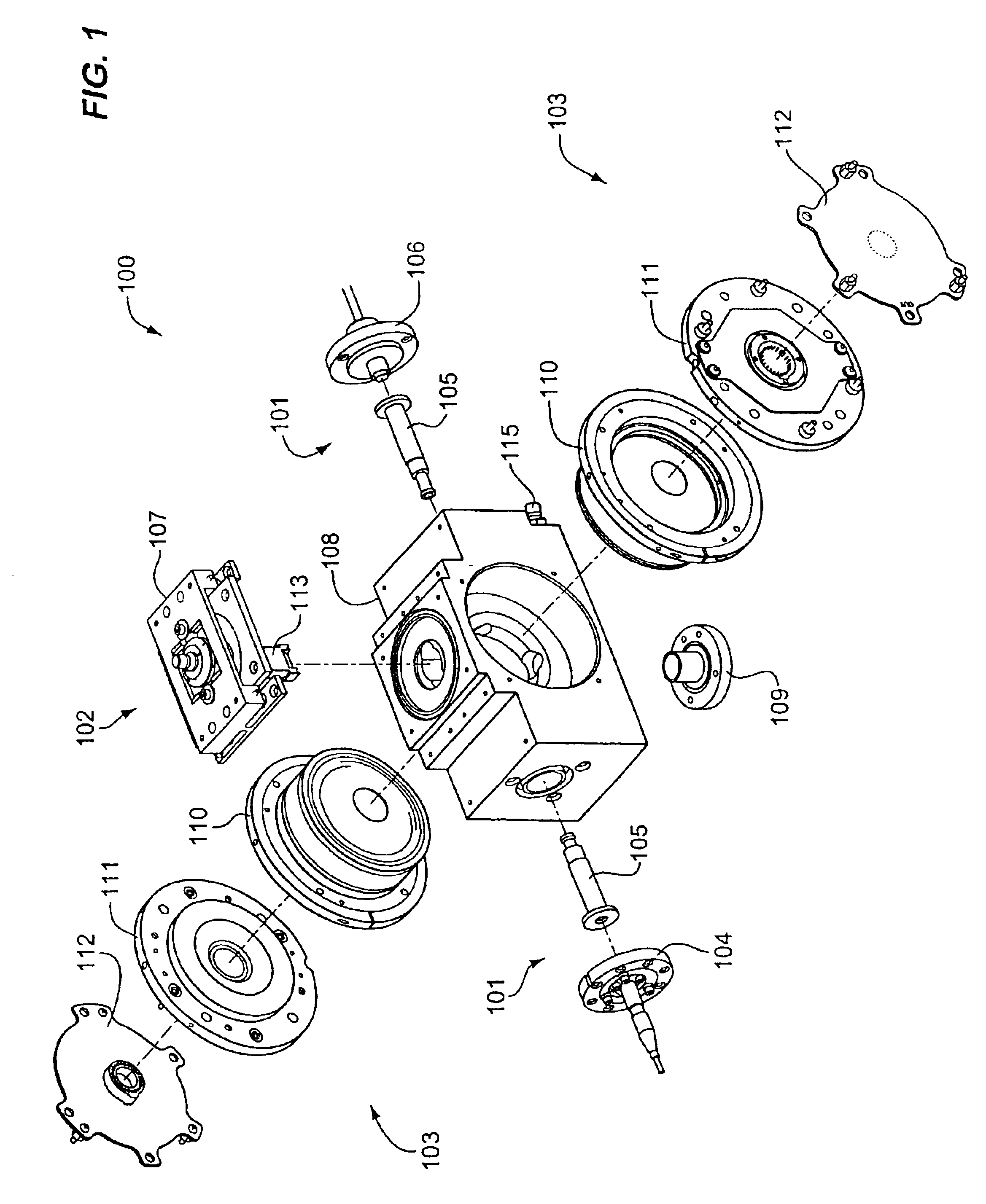
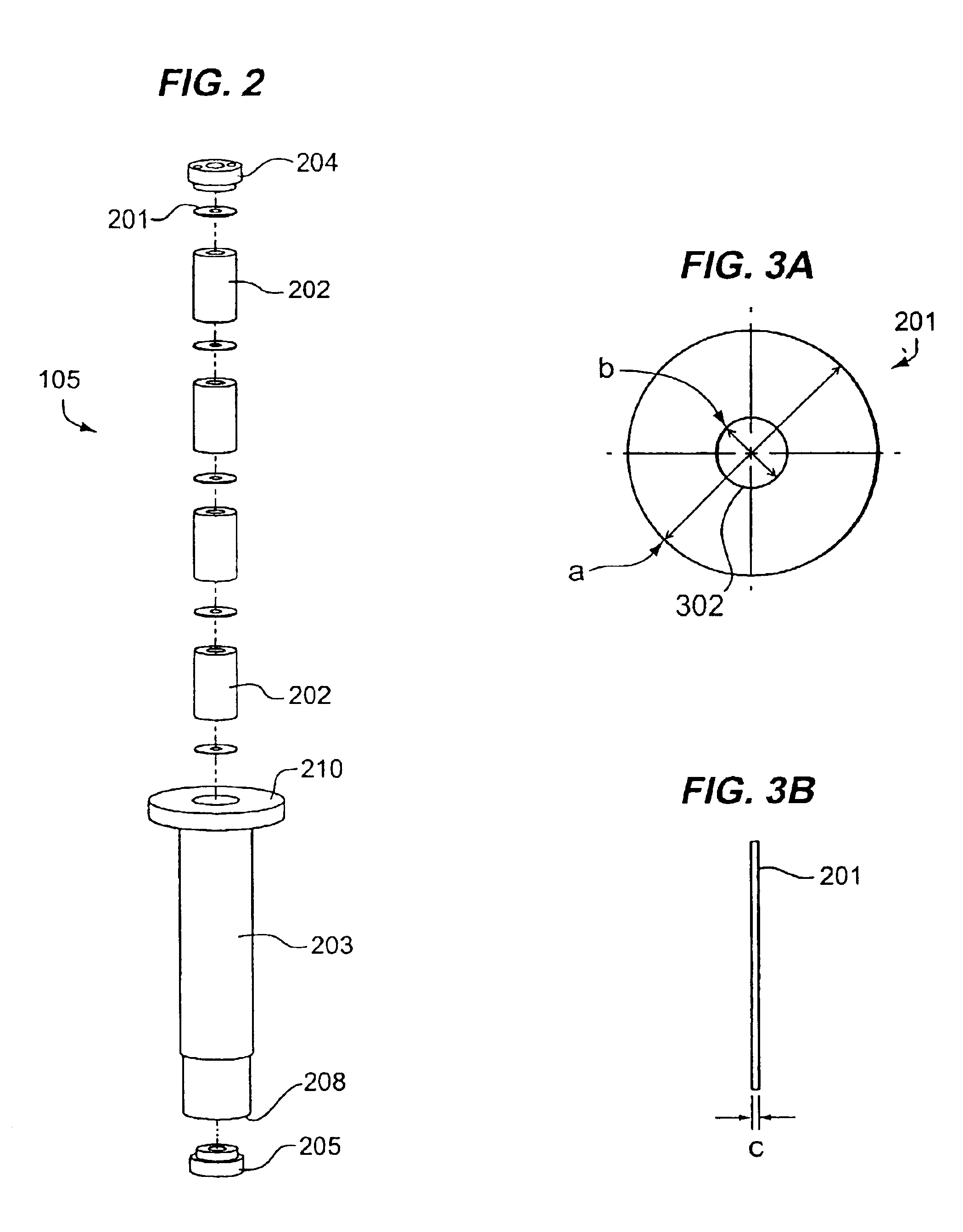
[0033]In this disclosure, an aperture assembly includes one or more physical apertures. An “aperture assembly” is equivalent to “light trap assembly”105 depicted in FIGS. 1, 2, and 4. In this disclosure “aperture,”“physical aperture,” and “aperture plates” are equivalent. In this disclosure, an “optical stop structure” is a structure for preventing diffuse laser light from reaching an orifice for fluid flow, located between this orifice and a source of laser light, or between the orifice and a laser cavity end mirror. A single optical stop structure may include one or more optical stops. A plurality of optical stops may be provided in a single optical stop str...


PUM


Abstract

An optical particle counter has a gain-apertured laser cavity producing laser light, an inlet jet providing fluid flow into a particle detecting region within the laser cavity, the inlet jet having an inlet jet orifice; a detection optics assembly located to collect light scattered from particles with the detecting region for producing an output signal indicative of the particles; and an optical barrier complex located to reduce noise as compared to the gain-apertured system without the optical barrier complex for fluid flow rates greater than or equal to about 0.1 cubic feet per minute. The optical barrier complex inhibits laser light from illuminating turbulent eddy currents originating on the interior walls of the inlet jet. The optical barrier complex includes one or more physical apertures, one or more optical stops, or both which are located to prevent laser light from illuminating the eddy currents.

Description

BACKGROUND OF THE INVENTION[0001]1. Field of the Invention[0002]The present invention relates in general to systems which utilize light scattering principles to detect and count undesirable particles in fluids, referred to in the art as light scattering particle counters, and more particularly to high power, low noise intracavity laser particle counters.[0003]2. Statement of the Problem[0004]The history of the semiconductor industry has shown a consistent path of steadily decreasing line widths. The semiconductor industry roadmap for the future shows this trend continuing unabated. Smaller semiconductor line widths mean smaller critical defect sizes, which in turn require detection of smaller particles, for effective contamination monitoring of clean room air. Accordingly, the semiconductor roadmap continually pushes researchers to develop ever more sensitive OPCs (optical particle counters), to measure ever smaller particle sizes. To achieve a statistically valid sample in a reason...

Claims


Application Information

Patent Timeline
IPC IPC(8): G01N15/14G01N21/53
CPCG01N15/14G01N2015/1486
Inventor CERNI, TODD A.SEHLER, DWIGHT A.LILLY, MARK A.
Owner PARTICLE MEASURING SYST
Why Eureka
Try Eureka