Bi-directional clutch having a momentary latching actuator

a momentary latching actuator and clutch technology, applied in the direction of clutches, non-mechanical actuator clutches, freewheel clutches, etc., can solve the problems of parasitic energy loss, drag, and relative rotation between the friction discs and the plates during open-pack mode, and achieve energy saving, great energy conservation, and increase efficiency

Inactive Publication Date: 2005-06-14
BORGWARNER INC
View PDF36 Cites 54 Cited by
  • Summary
  • Abstract
  • Description
  • Claims
  • Application Information

AI Technical Summary

Benefits of technology

[0017]Thus, the bi-directional clutch of the present invention overcomes the drawbacks of prior art clutches by being operable to selectively switch between the various modes of engagement by the momentary application of a control force. If one of the latching actuators is in the latched position, a single momentary application of a control force, in conjunction with constant return biasing force of the actuator will cause the actuator to index to its return position and remain there. If one of the latching actuators is in the return position, another single momentary application of the same control force, in conjunction with constant return biasing force of the actuator will cause the actuator to index to its latched position. This rapid and efficient change between the positions of the latching actuators moves the engagement mechanism of the clutch between its engagement modes. Therefore, the bi-directional clutch of the present invention moves between the modes of engagement efficiently and with great energy conservation. The latching feature of the actuators of the present invention provide further energy conservation and increases in efficiency by eliminating the need for a constant application of control force which also prevents clutch failures by maintaining the selected position in the absence of a constantly supplied control force.

Problems solved by technology

Relative rotation between the friction discs and the plates during open-pack mode creates drag.
This condition results in parasitic energy losses, reduces the efficiency of the transmission, transfer case or differential, and ultimately results in lower fuel efficiency.
For example, the friction clutch remains a source of significant parasitic losses due to inherent drag between the friction plates when the clutch is operating in “open pack” mode.
The use of a one-way overrunning clutch to selectively provide drive torque to a secondary driveline upon primary wheel slip has not, however, become a popular solution to part time 4WD vehicle requirements because of one problem: the clutch remains disengaged or inactive when reverse gear is selected unless, of course, the secondary driveline attempts to over speed the primary driveline.
Thus, in a situation frequently requiring 4WD, that is, when the vehicle may need to be rocked or simply backed over terrain, a 4WD configuration utilizing a one-way overrunning clutch will simply not provide 4WD operation.
This is a significant drawback of this clutch configuration.
While they appear to present a solution to certain problems identified above they have not been widely employed in transmission, transfer cases, and differentials of the related art.
These self-actuating bi-directional overrunning clutches are relatively mechanically complex and have certain physical limitations and drawbacks.
One such drawback is that the existing bi-directional clutches have a large angular distance from the engagement in one rotational direction to the engagement in the opposite rotational direction.
This makes for undesirable driving conditions by causing hard lockups when changing directions and also brings about a short mechanical life due to the severe inherent impact forces of the engagement.
Additionally, the self-actuating bi-directional clutches known in the related art cannot be selectively engaged in an efficient manner or to optimize the vehicle power output in response to varying driving conditions.
This has certain drawbacks and can cause particular operative problems.
If the electrical power to the solenoid is not maintained, the actuator discs may move in an uncontrolled manner to the opposite engagement position or to some point in-between.
In either case, an uncontrolled movement could be physically devastating to the clutch and its components and possibly other parts of the drivetrain.
At a minimum, an uncontrolled actuation of one, or both of the actuating discs would cause undesirable actions within the transfer case, or transmission, or other device in which the clutch may be installed.
This is problematic when one considers that any minor drop off in electrical power, or the occurrence of some type of momentary or prolonged electrical break would cause the actuator discs to be uncontrolled and free to randomly move.
Likewise, hydraulically controlled actuator discs suffer the same problem if a fluctuation, or drop off in hydraulic force where to occur.
A secondary consideration of selectively activated bi-directional clutches is that maintaining the electrical, or hydraulic pressure to the actuator requires a constant expenditure of energy.
This is a power requirement that must be accounted for in the design of the electrical or hydraulic support system, which ultimately adds to the size and cost of these systems.

Method used


Image

  • Bi-directional clutch having a momentary latching actuator
  • Bi-directional clutch having a momentary latching actuator
  • Bi-directional clutch having a momentary latching actuator

Examples


Embodiment Construction

)

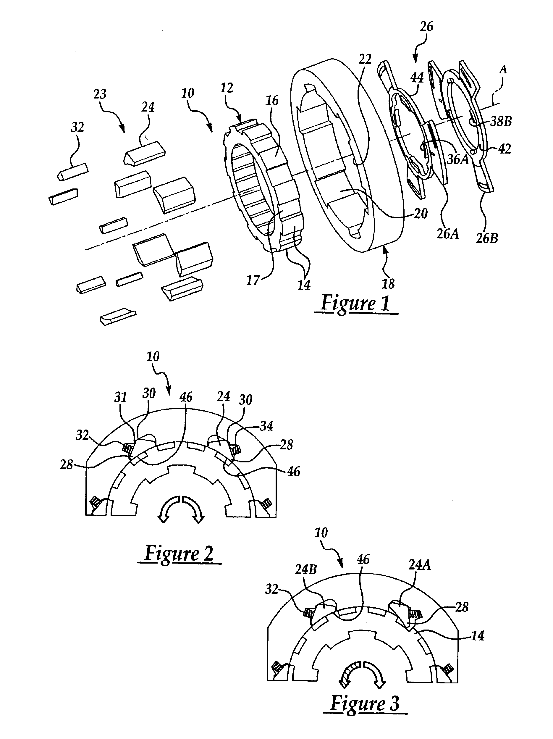
[0030]A bi-directional clutch assembly of the present invention having a latching actuator is generally indicated at 10 in the figures, where like numerals are used to designate like structure throughout the drawings. In the preferred embodiment illustrated herein, the clutch assembly 10 is operative in four different modes and is particularly adapted for use as a component of drivelines of land-based vehicles, such as in transmissions, transfer cases, differentials and the like. Accordingly, one application for the clutch assembly 10 of this particular type (i.e., having four operational modes) is for use in a motor vehicle transmission. However, those having ordinary skill in the art will appreciate that the clutch assembly 10 of the present invention may be employed in numerous applications, whether or not the application takes advantage of all four operational modes of the clutch assembly as discussed below.

[0031]Referring now to FIG. 1, the clutch assembly 10 of the present in...


PUM


Abstract

A bi-directional clutch assembly of the present invention is provided that comprises an inner race, an outer race, and an engagement mechanism disposed between said inner race and said outer race. The engagement mechanism is operable to move between a disengaged position wherein the inner and outer races may freely rotate relative to one another and an engaged position wherein the inner and outer races are locked so as to translate torque therebetween. The present invention also includes at least one actuator that is operatively connected to the engagement mechanism and responsive to a first momentary control force to selectively move the engagement mechanism to the engaged position and to hold the engagement mechanism in the engaged position after the first control force has been terminated. The actuator is further responsive to a sequentially applied second momentary control force to move the engagement mechanism to the disengaged position and to hold the engagement mechanism in the disengaged position after the second control force has been terminated and pending the selective application of a sequentially applied first control force.

Description

BACKGROUND OF THE INVENTION[0001]1. Field of the Invention[0002]The present invention relates, generally to bi-directional overrunning clutch assemblies and, more specifically, to a bi-directional clutch having a selectively controllable engagement assembly that is driven by an actuator that is operatively controlled by a momentary actuating force.[0003]2. Description of the Related Art[0004]Generally speaking, land vehicles require three basic components. These components include a power plant (such as an internal combustion engine), a power train and wheels. The power train's main component is typically referred to as the “transmission.” Engine torque and speed are converted in the transmission in accordance with the tractive-power demand of the vehicle. Transmissions include one or more gear sets, which may include an inner gear, intermediate planet or pinion gears that are supported by their carriers, and outer ring gears. Various components of the gear sets are held or powered ...

Claims


Application Information

Patent Timeline
Patent Type & Authority Patents(United States)
IPC IPC(8): F16D41/16F16D41/00
CPCF16D41/16
Inventor REED, CLYDE A.STEFINA, BRIAN K.
Owner BORGWARNER INC
Why Eureka
Try Eureka