
Method for fabricating a solar tile

a solar panel and manufacturing method technology, applied in the field of solar panels, can solve the problems of reducing efficiencies, requiring a more precise and expensive manufacturing process, and unable to generate the desired amount of voltage or current for single pv cells, so as to reduce cell edge, add mechanical stability and reliability, and reduce the effect of cell edg

Inactive Publication Date: 2005-06-14
GULA CONSULTING LLC
View PDF29 Cites 34 Cited by
  • Summary
  • Abstract
  • Description
  • Claims
  • Application Information

AI Technical Summary

Benefits of technology

[0010]In light of the foregoing background, the present invention provides a solar tile and method for fabricating the same employing a single coverslide and / or a flexible circuit that includes openings for receiving solder that extend completely through the circuit. The method of fabricating the solar tile of the present invention is capable of machine assembly and allows the solar cells to be placed such that a single coverslide covers the entire solar tile, as opposed to individual coverslides for each solar cell. The use of a single coverslide reduces cell edge and cell-to-cell interconnect exposure to damaging plasma radiation, and allows the solar tile to safely operate above 50 volts without conformal coating of the interconnects. The solar tile of the present invention may also include a flexible circuit that includes openings for receiving solder that extend completely through the circuit to allow solder connections to be inspected during fabrication of the solar tile which allows for greater solder connection integrity.
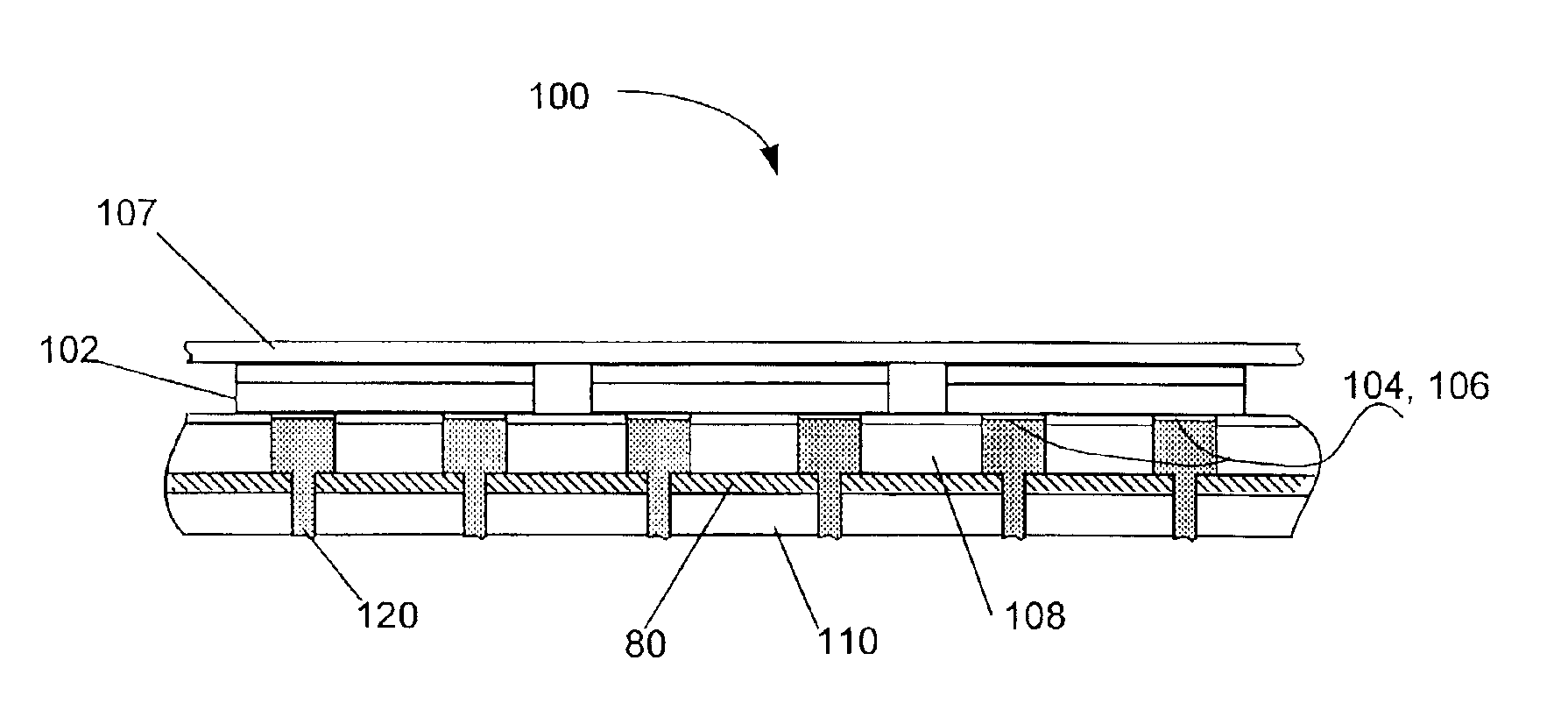
[0012]In one embodiment, each opening consists of an aperture, extending completely through one of the insulating sheets, and a hole, having a diameter smaller than the aperture, extending completely through the electrically conductive path and the other insulating sheet. The openings are capable of allowing a technician to inspect the electrically conductive solder connections. This helps insure solder connection integrity at the connection point between the solder connections and the solar cell contacts, and the solder connections and the electrically conductive path. The resulting solder connections adhere to their respective solar cell contacts and corresponding opening in the flexible circuit, providing interconnect structures between the electrically conductive path and the insulating sheets.
[0016]To insure solder connection integrity between the solder material and the solar cell contacts, and the solder material and the electrically conductive path, in one embodiment the solder material is inspected during reflowing of the solder material. In this embodiment, the solder material is viewed through the plurality of openings created through the insulating sheet opposite the plurality of solar cells to ensure that the solder material reflows. To add mechanical stability and reliability to the solar tile, the solar cells are secured to the flexible circuit by forming the solder connections so that the solder connections extend from a respective contact on the solar cell through a corresponding opening. In this embodiment, each solder connection preferably forms an interconnect structure between the electrically conductive path and the insulating sheets.
[0017]The present invention, therefore, provides a solar tile and method of fabrication that allow the solar cells to be placed such that a single coverslide covers the entire solar tile, allow inspection of solder connections during fabrication, and contain solder connections that form interconnect structures that add mechanical stability and reliability to the solar tile. The use of a single coverslide reduces cell edge and cell-to-cell interconnect exposure to damaging plasma radiation, and allows the solar tile to safely operate above 50 volts without conformal coating of the interconnects. Additionally, the flexible circuit defines openings completely therethrough that allow solder connections to be inspected during fabrication of the solar tile. Also, the solder material, deposited in the openings defined by the flexible circuit, forms interconnect structures for the solar tile.

Problems solved by technology

Due to the energy demands of many applications, a single PV cell generally cannot generate the desired amount of voltage or current.
But due to differences between environments, PV cells used for space applications generally require a more precise and, thus, costly manufacturing process.
But these alternatives have much lower efficiencies than Si or GaAs, generally making them impractical for space PV cells.
Typically, space PV arrays are hand-assembled and generally have non-uniform spacing between cells.
Additionally, hand assembly of space PV arrays typically decreases manufacturing precision.
The use of such pins, however, can lead to the damaging of the PV cells if the pins are misaligned relative to the cells or inaccurately moved in relation to the cells.
Not only do individual cover plates increase manufacturing cost for conventional space PV arrays, but they also typically result in both the cell edges and cell-to-cell interconnects being exposed to space plasma.
While mitigating damage to the cells, the lower voltage results in a significant harness loss for higher power applications, and conformal coating adds additional integration cost and mass to the array.

Method used


Image

  • Method for fabricating a solar tile
  • Method for fabricating a solar tile
  • Method for fabricating a solar tile

Examples


Embodiment Construction

[0025]The present invention now will be described more fully hereinafter with reference to the accompanying drawings, in which preferred embodiments of the invention are shown. This invention may, however, be embodied in many different forms and should not be construed as limited to the embodiments set forth herein; rather, these embodiments are provided so that this disclosure will be thorough and complete, and will fully convey the scope of the invention to those skilled in the art. Like numbers refer to like elements throughout.

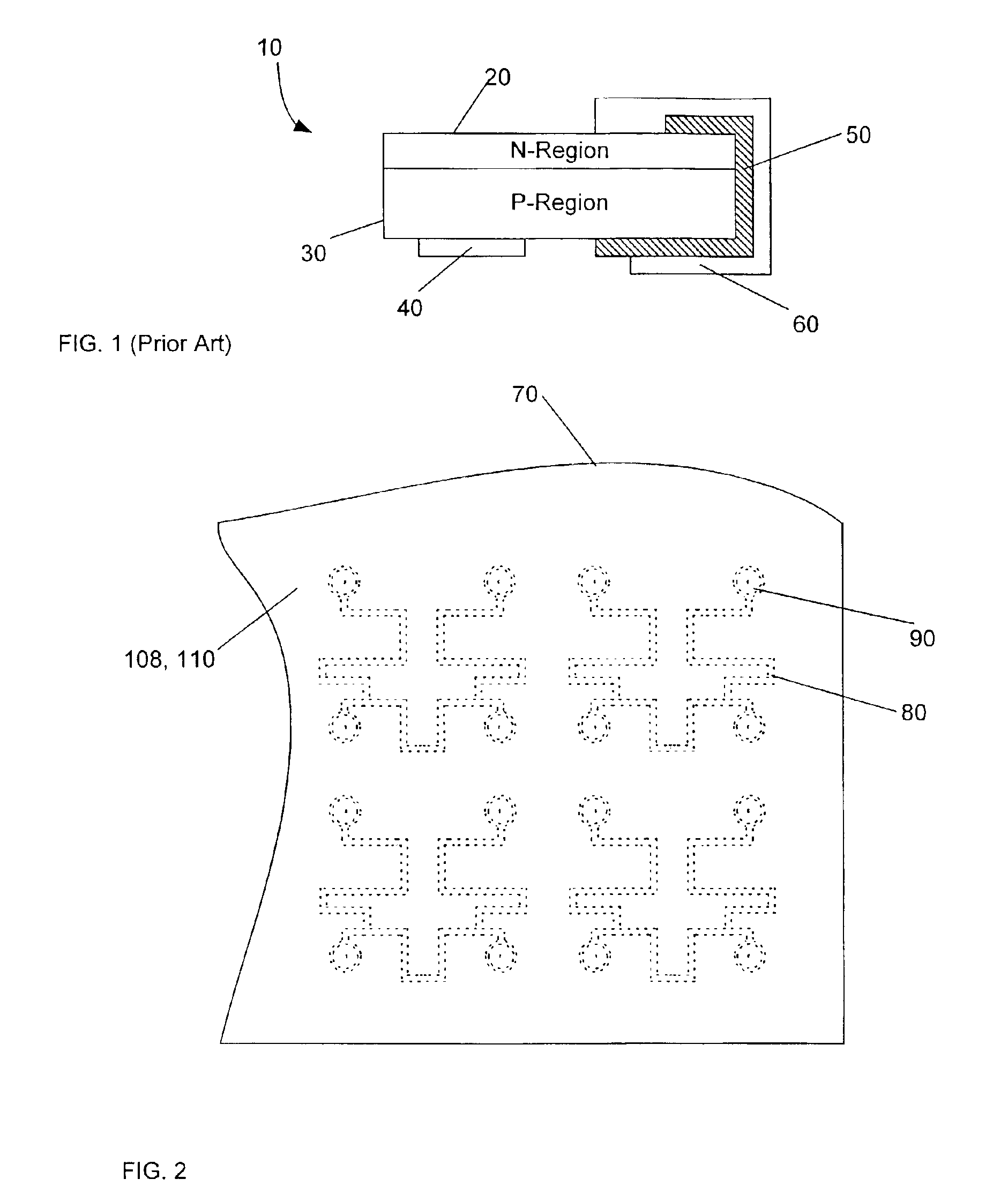
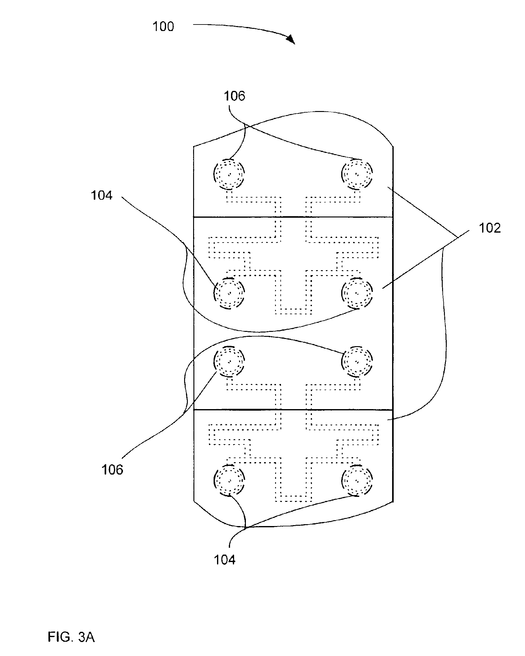
[0026]Referring to FIGS. 2, 3A and 3B, the solar tile 100 includes a flexible circuit 70 that comprises at least one electrically conductive path 80 laminated between front 108 and rear 110 insulating sheets. The electrically conductive path 80 interconnects the solar cells 102 that make up the solar tile 100 and, in a preferred embodiment, form a pattern within the insulating sheets 108, 110 such that a sufficient quantity of solar cells 102 can be interc...


PUM


Abstract

The present invention provides a solar tile and method for fabricating the same. The solar tile includes a flexible circuit having at least one electrically conductive path laminated between two insulating sheets. The flexible circuit includes a plurality of openings that are completely through the flexible circuit and define contact locations with the electrically conductive path. The solar tile also includes a plurality of coplanar photovoltaic solar cells that are secured to the flexible circuit so that the contacts are aligned with the openings in the flexible circuit. Further, the solar tile includes a plurality of electrically conductive solder connections located within the openings in the flexible circuit to electrically connect the solar cell contacts and the electrically conductive path. Additionally, in a preferred embodiment, the solar tile includes a single coverslide situated adjacent and covering the plurality of solar cells opposite the flexible circuit.

Description

CROSS-REFERENCE TO RELATED APPLICATIONS[0001]This application is a divisional of U.S. application Ser. No. 09 / 812,343, filed Mar. 20, 2001 now U.S. Pat. No. 6,476,314.FIELD OF THE INVENTION[0002]The present invention relates to solar tiles and, more particularly, to a solar tile having solar cells with coplanar contacts and method for fabricating the same employing a flexible circuit to interconnect a plurality of solar cells.BACKGROUND OF THE INVENTION[0003]Photovoltaic (PV) solar cells are used more extensively every day as an alternative energy source. Typically, a PV solar cell is used to provide solar power for a multitude of applications, both terrestrial and space. The more widespread of the two applications, terrestrial, mainly consists of solar powered consumer products, such as calculators, remote power applications, such as remote telecommunications power supplies, and utility generation applications, such as home electricity generation. Space solar power applications, on...

Claims


Application Information

Patent Timeline
Patent Type & Authority Patents(United States)
IPC IPC(8): H01L31/042H01L31/048H01L31/05H05K3/30H05K3/34H05K1/18
CPCH01L31/048H05K3/305H01L31/0516B64G1/443H05K1/189H05K3/341H05K2201/10121Y02E10/50H05K3/3442Y02P70/50
Inventor BAUMAN, JOHN SCOTTFLORA, CRAIG S.
Owner GULA CONSULTING LLC
Learn More