
Electronic circuit for ion sensor

Inactive Publication Date: 2005-06-14
CHUNG YUAN CHRISTIAN UNIVERSITY
View PDF4 Cites 82 Cited by
  • Summary
  • Abstract
  • Description
  • Claims
  • Application Information

AI Technical Summary

Benefits of technology

[0018]Furthermore, the disclosed ion sensing circuit acquires all the ISFET signals with no switching delay time. The circuit also can be promoted to satisfy the industry demands in mass production of ISFETs for more rapid, stable and accurate detection of their characteristics.

Problems solved by technology

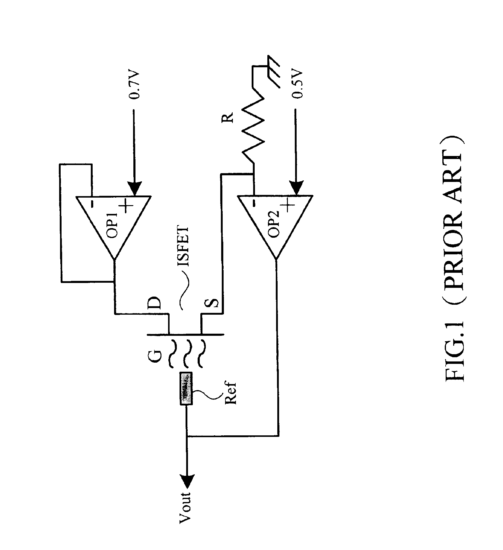
This is not economically viable, and is not suitable for mass production or commercial development.
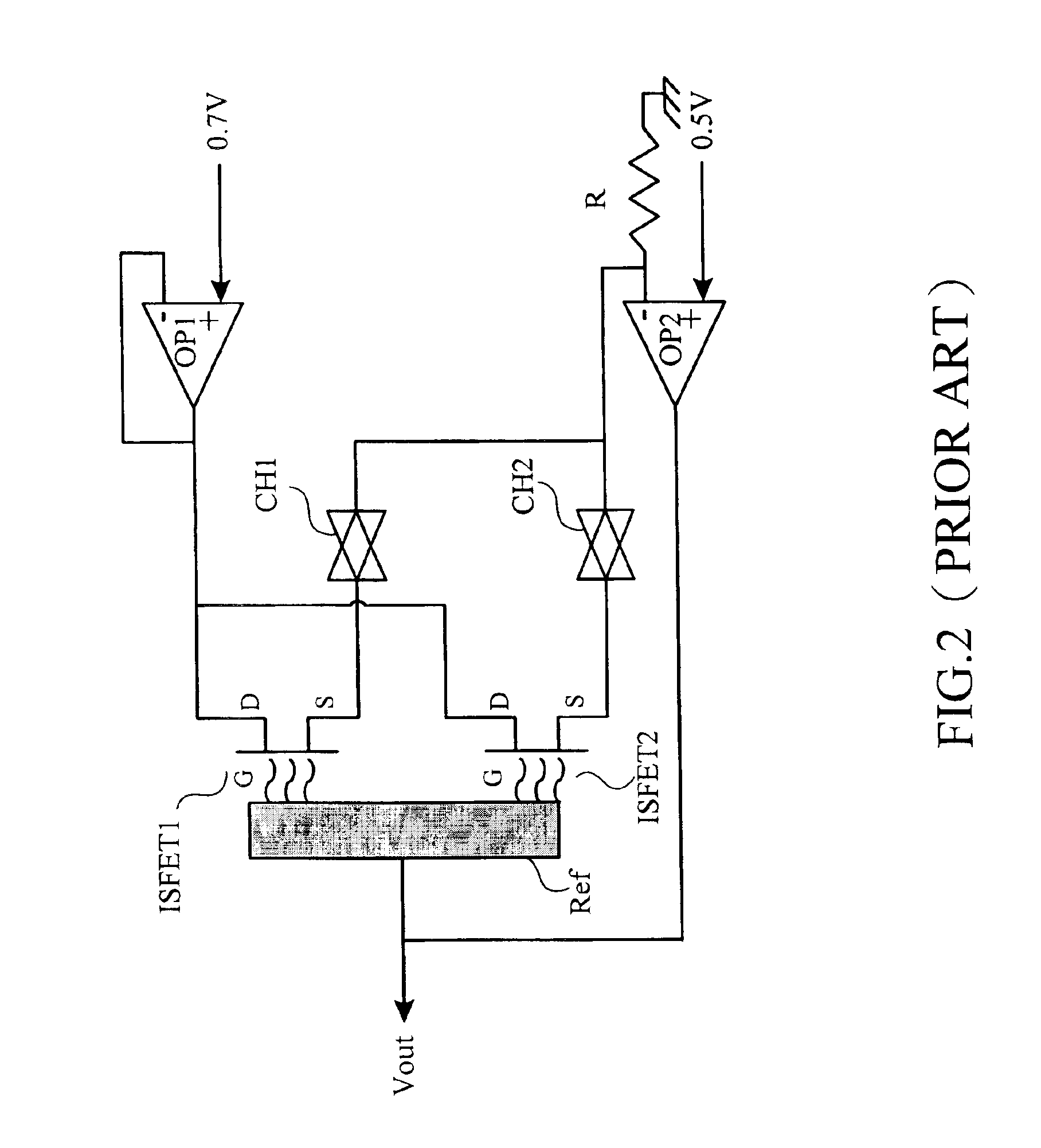
However, the problems of the conductivity of the switches, the rising temperature upon switching and noise interference need to be solved.
The situation is more serious when the number of ISFETs in the sensor array increases.
The detected signal implies the drift error of the ISFET owing to the switching time for completing the detection by ISFETs.
This may cause instability of the output signal Vout due to transient processes resulting from the switching.
Another drawback is increasing of measuring time resulting from the serial mode of operation and the above-mentioned transient processes.
The circuit in FIG. 3 is not suitably implemented by a standard CMOS technology.

Method used


Image

  • Electronic circuit for ion sensor
  • Electronic circuit for ion sensor
  • Electronic circuit for ion sensor

Examples


Embodiment Construction

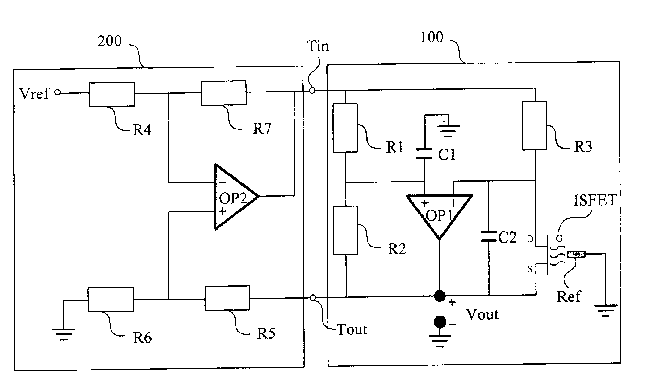
[0026]FIG. 4 illustrates the ion sensing circuit of the invention. The circuit in FIG. 4 can be implemented by integrated circuits. Bridge architecture is adopted in the bridge sensing circuit, in which the reference electrode Ref is grounded and the source terminal of the transistor ISFET floats due to its threshold voltage variation, which is output signal Vout.

[0027]The disclosed sensor can be placed directly into a solution. When the analyte to be measured reacts with the sensing membrane, the variation of the electric potential at the interface sensing membrane / solution results in changes of the gate-source voltage of the transistor ISFET and output signal Vout. The transistor ISFET is one kind of ion sensing element, which modulates the resistance of the channel between the drain and the source due to changes of the ion concentration in the solution.

[0028]As shown in FIG. 4, the bridge sensing circuit 100 is a bridged type circuit, which is composed of a first impedance elemen...


PUM


Abstract

An ion sening circuit comprises a bridge sensing circuit and a differential amplifying circuit. The bridge sensing circuit detects the ion concentration of the solution in the operation mode of constant voltage and constant current. The differential amplifying circuit compares the output of the bridge sensing circuit and a floating reference voltage, thereby the delivered voltage to the bridge sensing circuit, such that the opeation mode of constant voltage and constant current is formed accordingly. The main features of the disclosed circuit are that it grounds the reference electrode and floats the source terminal. The drawbacks of not being manufactured with intergrated circuits by CMOS technology and low benefits when applied to sensor arrays are avoided by the disclosed circuit.

Description

BACKGROUND OF THE INVENTION[0001]1. Field of Invention[0002]The invention relates to an ion sensing circuit, and more particular to a circuit adopting Ion-Sensitive Field Effect Transistors that is compatible with CMOS technology and implemented by integrated circuits.[0003]2. Related Art[0004]Silicon-based semiconductor micro sensors are now able to react to the ion concentration (activity). The Ion-Sensitive Field Effect Transistor (ISFET), which is a micro sensing element combining electrochemistry with microelectronics technology, was introduced in the 1970s. The ISFET selectively senses the ion concentration in an electrolyte. The ISFET is a trans-resistance element, which has the features of low output impedance of MOSFET and operation of Ion Selective Electrode (ISE). The ISFET has features of rapid reaction time, high sensitivity, batch processing, small size and single chip integration. Furthermore, it can be implemented by CMOS technology. These advantages make it the firs...

Claims


Application Information

Patent Timeline
IPC IPC(8): G01N27/414G01N27/403
CPCG01N27/4148
Inventor CHUNG, WEN-YAWKRZYSKOW, ALFREDLIN, YEONG-TSAIRPIJANOWSKA, DOROTA GENOWEFAYANG, CHUNG-HUANGTORBICZ, WLADYSLAW
Owner CHUNG YUAN CHRISTIAN UNIVERSITY
Learn More