Methods and apparatus for assembling rotatable machines

a technology of rotating machines and assembly methods, applied in the direction of machines/engines, climate sustainability, waterborne vessels, etc., can solve the problems of rotor vibration, rotor bearing and support structure stress, bearing support structure failure,

Inactive Publication Date: 2005-06-21
GENERAL ELECTRIC CO
View PDF13 Cites 19 Cited by
  • Summary
  • Abstract
  • Description
  • Claims
  • Application Information

AI Technical Summary

Benefits of technology

[0007]In yet another aspect, a computer system including a software product code segment for minimizing imbalance in a bladed rotor is provided. The segment is configured to receive a moment weight value for each blade to be installed in the rotor, receive a geometric parameter value for each blade to be installed in the rotor, calculate a blade location on the rotor based on the received values, and generate a blade map based on the calculated location.

Problems solved by technology

An imbalance of the rotor may cause vibration of the rotor and induce stresses to rotor bearings and support structures.
Over time, continued operation with such stresses may lead to failure of the bearings, bearing support structure, and / or rotor components.
Failure of a component within the engine system may damage the system and / or other components within the system, and may require system operations be suspended while the failed component is replaced or repaired.
More particularly, when the component is a turbofan gas turbine engine fan blade, a blade-out condition may cause damage to a blade that is downstream from the released blade.
However, because the geometry of adjacent blades may be different, during operation a rotor may still experience a shift in balance that is not associated with the moment weight of each blade.

Method used


Image

  • Methods and apparatus for assembling rotatable machines
  • Methods and apparatus for assembling rotatable machines
  • Methods and apparatus for assembling rotatable machines

Examples


Embodiment Construction

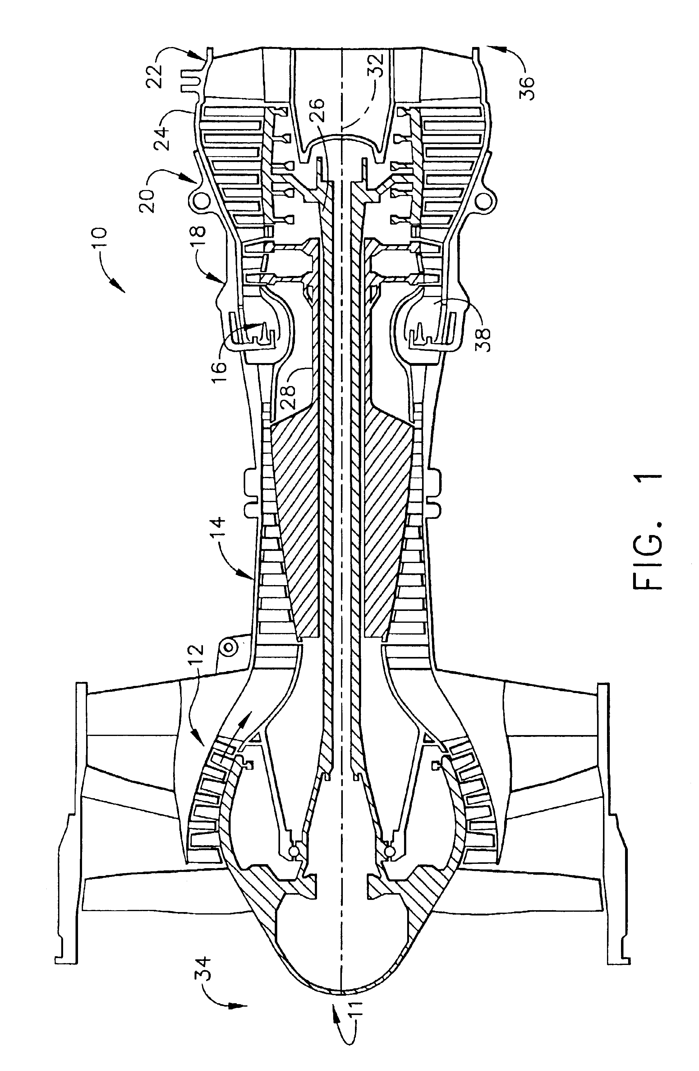
[0012]FIG. 1 is a schematic illustration of an exemplary gas turbine engine 10 including a rotor 11 that includes a low-pressure compressor 12, a high-pressure compressor 14, and a combustor 16. Engine 10 also includes a high-pressure turbine 18, a low-pressure turbine 20, an exhaust frame 22 and a casing 24. A first shaft 26 couples low-pressure compressor 12 and low-pressure turbine 20, and a second shaft 28 couples high-pressure compressor 14 and high-pressure turbine 18. Engine 10 has an axis of symmetry 32 extending from an upstream side 34 of engine 10 aft to a downstream side 36 of engine 10. In one embodiment, gas turbine engine 10 is a GE90 engine commercially available from General Electric Company, Cincinnati, Ohio.

[0013]In operation, air flows through low-pressure compressor 12 and compressed air is supplied to high-pressure compressor 14. Highly compressed air is delivered to combustor 16. Combustion gases 38 from combustor 16 propel turbines 18 and 20. High pressure tu...


PUM

PropertyMeasurementUnit
weightaaaaaaaaaa
moment weight vector sumaaaaaaaaaa
aerodynamic balanceaaaaaaaaaa

Abstract

A method and apparatus for assembling a rotatable machine is provided. The machine includes a plurality of blades that extend radially outwardly from a rotor. The method includes determining a moment weight of each blade in a row of blades, determining a geometric parameter of each blade in the same row of blades, and determining a mapping order of each blade using the moment weight and the geometric parameter. The apparatus includes a computer system that includes a software product code segment for minimizing imbalance in a bladed rotor wherein the segment is configured to receive a moment weight value for each blade to be installed in said rotor, receive a geometric parameter value for each blade to be installed in said rotor, calculate a blade location on the rotor based on the received values, and generate a blade map based on the calculated location.

Description

BACKGROUND OF THE INVENTION[0001]This invention relates generally to gas turbine engines and, more particularly, to assembling rotating components of gas turbine engines.[0002]At least some known gas turbine engines include a core engine having, in serial flow arrangement, a fan assembly and a high pressure compressor which compress airflow entering the engine. A combustor ignites a fuel-air mixture which is then channeled through a turbine nozzle assembly towards low and high pressure turbines which each include a plurality of rotor blades that extract rotational energy from airflow exiting the combustor. Gas turbines are used in different operating environments, such as, to provide propulsion for aircraft and / or to produce power in both land-based and sea-borne power systems.[0003]During normal operation gas turbine engines may experience high rotational speeds. An imbalance of the rotor may cause vibration of the rotor and induce stresses to rotor bearings and support structures....

Claims


Application Information

Patent Timeline
Patent Type & Authority Patents(United States)
IPC IPC(8): F01D5/00F01D5/02F01D5/30F04D29/66F01D5/10F02C7/00F04D29/32F04D29/34
CPCF01D5/027F01D5/30F01D5/3007F04D29/662Y02T50/671F05D2230/60Y10S416/50Y10T29/49321Y02T50/673Y02T50/60
Inventor HENNING, THOMAS RICHARDVAN DER MERWE, GERT J.RUEHR, WILLIAM CARLMOLLMANN, DANIEL EDWARD
Owner GENERAL ELECTRIC CO
Why Eureka
Try Eureka