Electronic ballast and electronic transformer

US6909246B2Inactive Publication Date: 2005-06-21TRIDONIKATKO GMBKH & KO KG

Image

  • Electronic ballast and electronic transformer
  • Electronic ballast and electronic transformer
  • Electronic ballast and electronic transformer

Examples


Embodiment Construction

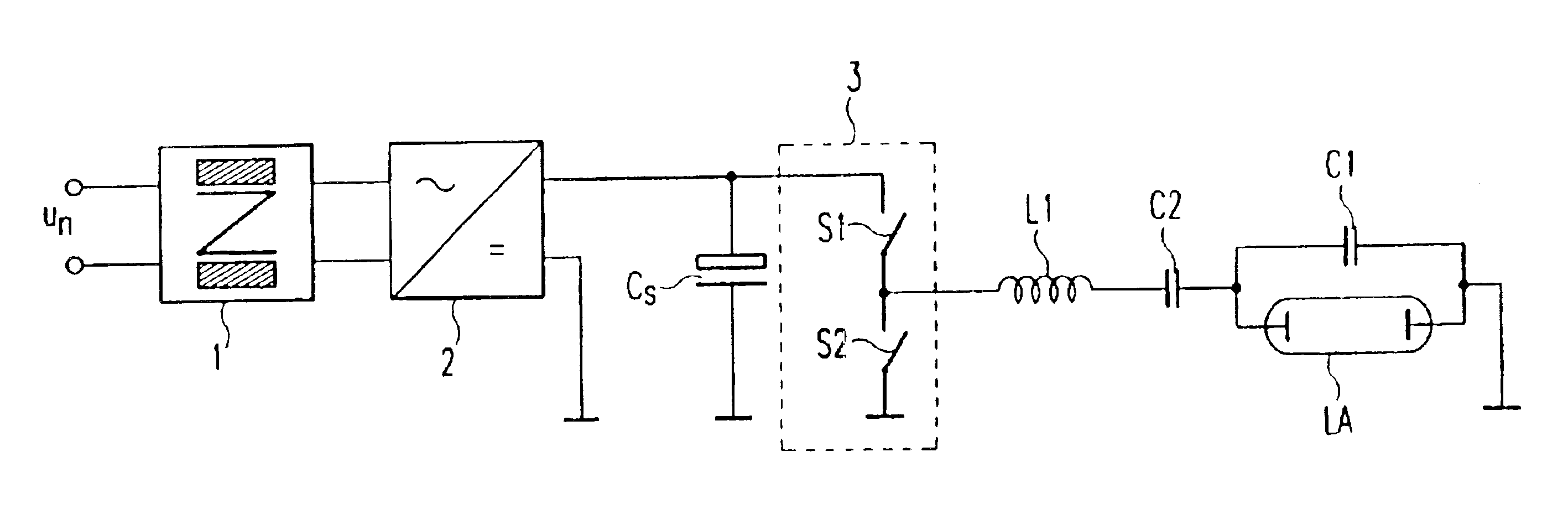
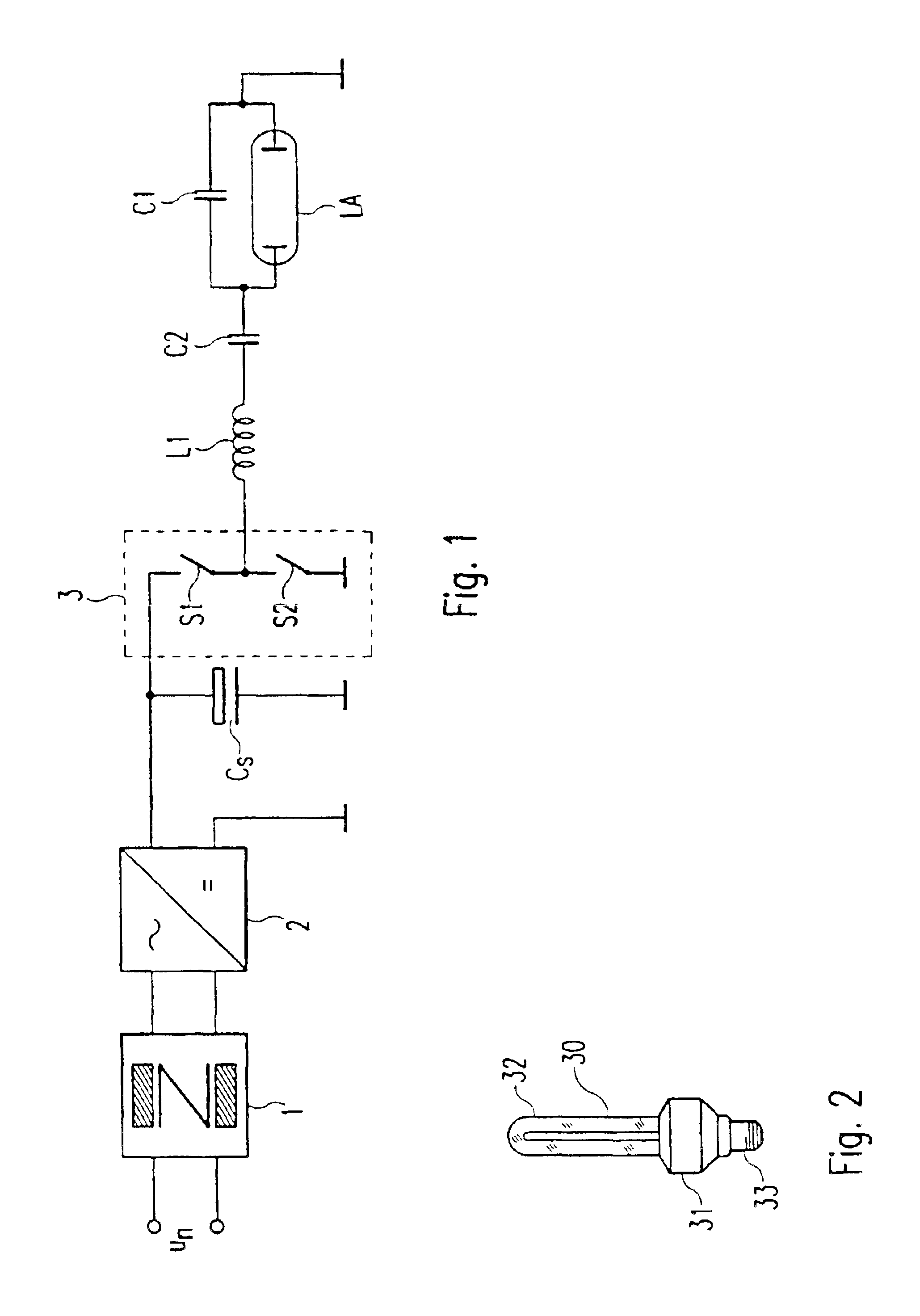
[0038]FIG. 1 shows the typical operating circuit diagram of a simple electronic ballast. The input of the ballast connected to the mains alternating voltage un is formed by a harmonic filter 1, which is intended as an interference suppression filter to limit the interference voltages arising due to the switching operations in the ballast and spreading to the supply system. Connected to the output of the harmonic filter 1 is a rectifier circuit 2 - for example a bridge rectifier or the like. To smooth the rectified mains alternating voltage un, an electrolytic capacitor Cs acting as a storage capacitor is located between the positive output of the rectifier circuit 2 and the input of the inverter 3.

[0039]In the present example, the inverter 3 of the ballast is formed by a half-bridge of two series-connected electronic switches S1 and S2, it being possible for one switch respectively to consist of a MOS field-effect transistor. These two switches S1 and S2 are driven via a control cir...


PUM


Abstract

An electronic ballast which includes a resonant load circuit (L1, C1) in series with a discharge lamp (LA), the resonant load circuit being supplied by an inverter (S1, S2) which outputs variable alternating voltages at frequencies above 200 KHZ. Alternatively, an electronic transformer incorporates a load circuit and a variable output frequency inverter for operating a low volt halogen lamp (7) at variable alternating frequencies above 200 KHZ. Passive components of the ballast and transformer are integrated into a multilayer circuit (13).

Description

CROSS REFERENCE TO RELATED APPLICATIONS[0001]This is a continuation of copending International Application No. PCT / EP00 / 13170, filed Dec. 22, 2000, which was published as WO 01 / 49083 on Jul. 5, 2002 in German but not in English, and the priority of which is hereby claimed.BACKGROUND OF THE INVENTION[0002]1. Field of the Invention[0003]The invention relates to an electronic ballast for operating a discharge lamp that has electrodes and an electronic transformer for operating a low-volt halogen lamp.[0004]2. Description of the Related Art[0005]The designer of electronic ballasts cannot help thinking first of all of operating any ballast he is to design at the mains frequency, as the mains frequency is available. However, it proves to be the case here that relatively large components have to be selected. A consequence of this is that the ballast is not only expensive, but also that its rates of wear are still relatively great.[0006]Ballast designers have therefore gone over very quickl...

Claims


Application Information

Patent Timeline
21 Jun 2005
Publication
US6909246B2
IPC
H05B41/282; H05B41/28; H05K1/16
CPC
H05B41/282; H05B41/2827; Y02B20/183; H05K1/165; Y02B20/00
Inventors
HEIN, PETER